





Using Amorphous Alloy Distribution Transformers in Rural Networks With Long Energized Hours
In a rural network that remains energized day and night, a transformer consumes energy even when local demand is low. That is why an amorphous alloy distribution transformer deserves serious consideration where feeder loads are dispersed, seasonal, or modest for long periods. Its value is not simply that it is “efficient”; it is that lower core loss can reduce the cost of keeping a large number of distribution points continuously energized.
The decision still depends on the network. A transformer with very low no-load loss will not correct an undersized conductor, excessive feeder length, poor phase balancing, or a badly located transformer. The best results come from treating the transformer as one part of a rural voltage-quality and loss-reduction plan, rather than as a stand-alone energy-saving purchase.
Why long energized hours change the transformer decision
Transformer losses have two different operating patterns. No-load loss, often called core loss, is present whenever the transformer is energized. It changes little with customer demand. Load loss rises as current passes through the windings, so it becomes more important when the transformer operates heavily loaded.
Rural distribution networks commonly have a high proportion of energized time relative to average transformer loading. A village transformer may remain in service around the clock while demand rises only during morning, evening, irrigation, processing, or local business hours. In such a profile, continuous core loss can represent a meaningful share of annual energy loss.
Amorphous metal cores are designed to reduce magnetization loss in the core. This makes an amorphous alloy distribution transformer particularly relevant for installations that stay energized for long periods but do not run close to rated load all day. Conventional core-steel units can remain appropriate in other duty cycles, especially where load losses, fault duty, available space, or a standardized replacement fleet carry more weight. The correct choice is based on the expected load profile, not the transformer label alone.
Start with the network profile, not the nameplate rating
A common procurement error is to compare transformers only by rated capacity and purchase price. Capacity is necessary for safe operation, but it does not show how much energy the unit will waste while energized or whether it will provide usable voltage at the end of a long low-voltage line.
Before selecting the transformer, assemble a practical picture of each proposed location:
- Hourly or seasonal load behavior, including irrigation, harvest processing, refrigeration, workshops, and evening residential demand.
- Expected load growth, with a clear distinction between firm new demand and uncertain future development.
- Length and conductor size of the medium-voltage and low-voltage feeders.
- Existing voltage complaints, particularly at remote customers during peak periods.
- Phase imbalance caused by uneven single-phase connections.
- Likely harmonic-producing loads, such as variable-speed drives, welders, chargers, or power electronic equipment.
- Site conditions: lightning exposure, access roads, flooding, dust, salt contamination, and ambient temperature.
This information identifies whether the project is primarily a no-load-loss problem, a voltage-drop problem, a capacity problem, or a combination. It also prevents a familiar outcome: installing an efficient transformer at an unsuitable point on the network and then finding that voltage quality has barely improved.
For networks with a large number of lightly loaded, permanently energized transformers, evaluating annualized losses is more useful than comparing a single efficiency figure at one load point. The purchasing comparison should include guaranteed no-load loss, load loss at the applicable reference temperature, anticipated loading pattern, energization hours, and expected service life. Installation cost, inspection access, spares strategy, and outage consequences should be included as well.
Where amorphous-core units fit well
The strongest application is a distribution point with long connection time and a modest or variable load factor. Typical examples include scattered residential villages, rural public services, small agricultural communities, telecom support loads, and feeders serving customers whose peaks occupy only part of the day.
They can also be useful when a network upgrade replaces numerous aging, high-loss units. In that situation, the accumulated reduction in continuous core loss across the fleet can matter more than the benefit at any one transformer. A uniform specification can simplify maintenance, but only when it still allows for different mounting arrangements, voltage ratios, tap requirements, and environmental conditions.
They are not automatically the preferred answer for every rural transformer. A location with sustained high loading needs close attention to winding loss, temperature rise, impedance, overload requirement, and cooling arrangement. A transformer chosen solely for low core loss may not be the best lifecycle option if it is regularly driven near its thermal limits. Likewise, a short-duration construction supply or a site expected to be quickly replaced by a larger substation may not justify a premium solution.
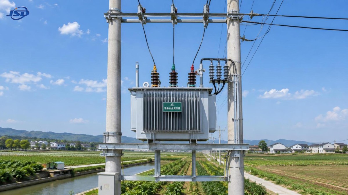
Voltage performance requires a placement decision
In rural projects, the transformer is often expected to solve two problems at once: reduce losses and improve customer voltage. It can help with both, but the placement rule matters. Moving transformation closer to a concentrated low-voltage load can shorten the low-voltage run and reduce voltage drop. Extending the medium-voltage line instead may be preferable when that reduces current over the longer section of the route.
The optimum point cannot be chosen from a map alone. It should reflect conductor resistance and reactance, maximum diversified load, motor starting demand, and the ability to maintain the installation. A transformer placed close to a small present load but far from anticipated growth can create an expensive second relocation or parallel installation later.
Tap settings also need discipline. A tap position that makes voltage look acceptable at a lightly loaded commissioning condition may create excessive voltage when load falls, or insufficient voltage during the actual evening peak. Record the upstream voltage range and assess the expected low-voltage condition at the farthest meaningful point. When off-circuit taps are used, the selected position should be documented on the commissioning record and revisited after the network has experienced its normal operating cycle.
Specification details that should not be left vague
An amorphous core does not remove the normal engineering requirements of a distribution transformer. The purchase specification should be clear about system voltage, frequency, winding connection, vector group where applicable, neutral arrangement, rated capacity, impedance, insulation level, tap range, mounting type, and required test documentation. Ambiguous specifications often create site problems that are mistakenly blamed on the core technology.
For pole-mounted units, confirm lifting points, mass limitations, mounting geometry, clearances, terminal orientation, and the ability of the structure to withstand local wind and conductor forces. For ground-mounted transformers, consider drainage, flood elevation, enclosure access, cable bending space, public protection, and vehicle impact exposure. A compact layout is useful only if technicians can safely inspect bushings, earthing connections, labels, and protective devices.
Core material also warrants practical handling requirements. Amorphous alloy strips have different mechanical characteristics from conventional electrical steel. The transformer should be transported, lifted, and installed in accordance with the manufacturer’s instructions, with particular care to avoid unnecessary shock or improper handling. This is not a reason to avoid the technology; it is a reason to make transport and receiving inspection part of the project plan.
Protection and earthing remain central to reliability
Rural overhead lines are frequently exposed to lightning and switching disturbances. A low-loss transformer can still suffer early failure if arresters, earthing, fuse coordination, and clearances are poorly designed. Confirm that surge arresters are correctly positioned and connected with short, practical leads; establish an earthing arrangement suited to local soil conditions; and coordinate primary protection with the transformer’s inrush behavior and available fault levels.
Do not treat repeated fuse operations as a routine inconvenience. They may indicate an undersized transformer, unbalanced loading, a line fault, unsuitable fuse selection, inrush-related operation, or a developing internal issue. The response should be evidence-based: inspect the event pattern, load data, connections, and protection settings before changing equipment ratings.
Commissioning that protects the lifecycle case
Commissioning should confirm more than whether the unit energizes. Check the nameplate against the approved design, verify tap position, inspect bushings and terminals, confirm oil level or enclosure condition as applicable, test earthing continuity, and ensure that arresters and fuses match the installation drawings. Record the initial voltage at the transformer and representative remote points under the available load condition.
After the network has entered normal service, compare actual demand with the planning assumptions. This step is especially valuable in rural developments where load can shift rapidly after connection. A transformer that remains lightly loaded is likely delivering the intended no-load-loss benefit. A unit that begins carrying sustained higher current may need a review of thermal margin, phase allocation, and future reinforcement timing.
Routine field inspections should focus on visible and measurable warning signs: loose or overheated terminals, damaged arresters, oil leaks where relevant, unusual sound, corrosion, vegetation encroachment, compromised fences, and changes in load balance. Remote monitoring can be useful at critical or inaccessible locations, but it should support a defined maintenance response rather than generate data that nobody owns.
When storage belongs in the same rural upgrade
Energy storage and transformer efficiency address different problems. An amorphous-core transformer reduces energy wasted while energized. Storage can shift local demand, support a short-duration peak, improve renewable-energy use, or provide backup to a defined load. It should not be selected as a substitute for correcting inadequate transformer capacity, poor protection, or severe feeder voltage drop.
Where a rural project includes a commercial processing site, charging point, or renewable-energy facility with concentrated low-voltage demand, storage may be evaluated alongside the transformer and feeder design. An outdoor integrated option such as the 125kW/261kWh Commercial & Industrial Energy Storage System can be relevant when peak shaving, load shifting, backup operation, and monitored operation are defined project requirements. Its role should be based on the local load study and interconnection design, not added merely because the network includes an efficient transformer.
A practical approval sequence
- Map each transformer location, feeder length, present load, anticipated load, voltage concern, and access constraint.
- Separate locations dominated by continuous energization from those dominated by high current and short peak demand.
- Compare proposed transformer options using no-load loss, load loss, expected operating profile, and service requirements.
- Verify placement and tap strategy against voltage conditions at the far end of the low-voltage network.
- Specify protection, earthing, mounting, transport, and acceptance requirements with the same care as the core-loss target.
- Commission with records that make later troubleshooting possible, then review real loading after normal operation begins.
Jinshida Electric Power Technology Co., Ltd. supports power transmission and distribution projects with an emphasis on safe, energy-efficient, and dependable equipment. For rural network work, the useful supplier contribution is not only supplying a transformer but helping translate the feeder profile, site environment, installation arrangement, and operating objective into a specification that can be built, installed, and maintained reliably.
The soundest rural deployment is usually selective rather than universal: apply low-core-loss transformers where long energized hours make them valuable, strengthen the network where voltage drop or conductor loss is the real constraint, and reserve capacity and storage measures for locations whose demand profile justifies them. That approach protects both technical performance and long-term operating cost.

Get a Quote
Regardless of whether you require general advice or specific support, we are happy to help you.
Send Us Your Inquiry Today

Jinshida Electric remains committed to contributing to global energy development through professional manufacturing and superior service.