





Managing Inrush Current and Noise in Amorphous Alloy Distribution Transformer Projects
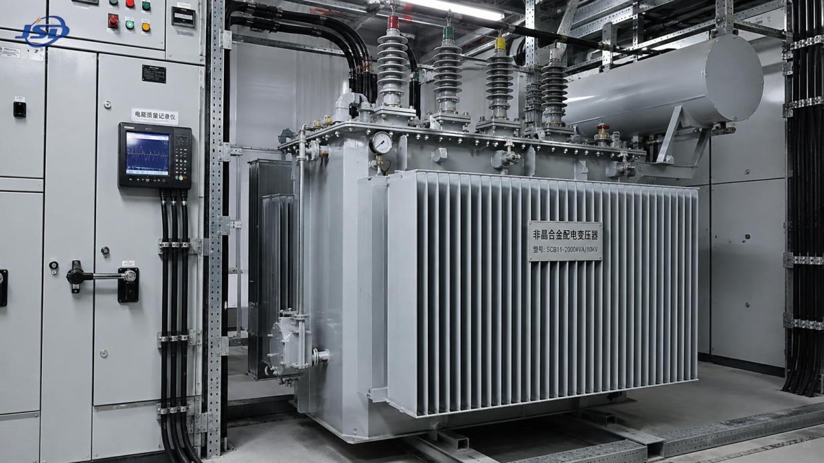
Control of inrush current begins before the transformer is energized. An amorphous alloy distribution transformer can draw a high, asymmetric magnetizing current when core flux is driven beyond its normal operating range during switching. The event is brief, yet it can trip upstream protection, depress the local voltage, stress switchgear contacts, and create a loud mechanical sound that is easily mistaken for an internal fault.
The first diagnostic question is whether the sound and current occur only during energization or persist afterward. A short, forceful hum or knock accompanied by a transient current surge points toward inrush. Continuous elevated current, sustained vibration, abnormal temperature rise, or recurring protective operation requires a wider investigation. Treating every loud energization event as a winding defect can lead to unnecessary internal inspection, while dismissing persistent noise as normal inrush can delay correction of a serious condition.
Why Amorphous Cores Need Careful Switching Assessment
Amorphous alloy core material is selected primarily for low no-load loss. Its magnetic behavior also makes the energization condition important. The actual core flux immediately after closing is determined by the residual flux left from the prior de-energization, the point on the voltage wave at which the switching device closes, and the applied voltage. If the new flux waveform adds to residual magnetism in the same direction, the core can enter deep saturation for part of a cycle.
During saturation, magnetizing inductance falls sharply. Current is then limited mainly by winding resistance, source impedance, and leakage reactance rather than normal magnetizing impedance. The resulting waveform is rich in harmonics and often strongly asymmetric. A current reading with insufficient sampling speed may show only a vague peak or an apparently unbalanced phase, so event records from a suitable power-quality recorder or relay disturbance file are more useful than a routine clamp-meter reading.
Residual flux is not a fixed nameplate property. It changes with the instant of opening, the interruption characteristics of the switching device, and the way the transformer was previously loaded. A unit that energizes quietly on one occasion can have a severe inrush event after a different shutdown sequence. This explains why replacing a transformer solely because one energization produced an abnormal sound is rarely justified without corroborating evidence.
Separate Inrush Sound from Persistent Mechanical Noise
Core magnetostriction produces a normal audible hum under excitation. Inrush causes a different mechanical response because high flux density creates a rapid increase in magnetic force. The sound is often more abrupt, lower in tone, and may include a single impact-like component as the core, clamps, tank panels, or cable supports respond to the force. It should decay as the transient current subsides.
A sound that remains at a stable level after energization deserves a controlled comparison. Record it at no load and at several load levels where operating conditions allow. Noise that is nearly unchanged with load is more likely associated with the core, core clamping, tank resonance, applied voltage, or loose external hardware. Noise that increases with load can be related to winding electromagnetic forces, loose leads, cooling equipment, or load-current harmonics. The distinction is useful, but it is not absolute; a loose tank cover, for example, can amplify both core and winding vibration.
Read the Switching Event as a System Event
Transformer inrush is shaped by the network around the transformer. A stiff supply can deliver a high peak current with less visible voltage sag. A weaker feeder may limit the current peak but cause a deeper voltage dip, which can disturb contactors, variable-speed drives, or other sensitive loads. Neither result alone proves that the transformer is defective.
Three-phase energization needs particular attention. Breaker poles do not always close at exactly the same instant. Pole scatter can create unequal flux conditions among phases, and the recorded transient can look like a phase fault if it is examined without the switching timeline. Verify the breaker auxiliary contact indications against the current onset. Where the event occurs through a circuit breaker with known mechanical wear, repeated timing tests can reveal a closing pattern that is becoming inconsistent.
Source transformer connections and grounding arrangements also affect the visible waveform. Zero-sequence paths, CT placement, and differential relay connections influence how the transient is represented to protection. Before changing relay pickup values or blocking functions, compare the relay event record with primary currents and confirm CT polarity, ratio, and secondary wiring. A protection adjustment made to suppress a misinterpreted signal can reduce sensitivity to a real fault.
Measurements That Clarify the Cause
Start with an operating history rather than a single sound report. Note the de-energization method, outage duration, feeder configuration, tap position, load status before opening, weather conditions, and whether capacitor banks or distributed generation were connected. These details establish whether the event followed a repeatable switching sequence or appeared after a network change.
Capture phase currents and voltages from before closing through the decay of the transient. The useful record shows waveform shape, not merely RMS values. A typical inrush waveform has a pronounced offset and substantial second-harmonic content, although harmonic characteristics alone should not be used as a final diagnosis. Modern core designs, operating voltage, CT saturation, and the duration of the transient all affect the harmonic ratio seen by a relay.
Measure the voltage at the transformer terminals, not only at a remote bus if practical. Sustained voltage above the intended operating condition raises no-load excitation and can make normal magnetostriction noticeably louder. Confirm tap-changer position against the actual supply voltage and transformer rating. A tap position chosen for a lower feeder voltage may produce excessive excitation after a network voltage adjustment.
Vibration measurements are valuable when the sound continues. Take readings at consistent locations on the tank wall, cover, radiator supports, cable boxes, and accessible structural members. A sharp local vibration peak at a cover or guard often identifies a resonance or loosened fastener rather than an active-core problem. Do not tighten core clamps blindly. Internal clamp force and insulation clearances are design-dependent, and unauthorized adjustment can damage the core or create a different vibration path.
Corrections That Match the Failure Mode
If records show a normal inrush event but protection trips, review the restraint and coordination philosophy before modifying hardware. Differential protection commonly uses an inrush discrimination method, while feeder overcurrent protection must tolerate a legitimate transient without losing fault discrimination. The correct settings depend on transformer rating, source fault level, CT performance, downstream load behavior, and the expected switching arrangement. A setting change should be validated against available fault and inrush records, not based on the peak current from one event.
Where repeated energization is operationally necessary, controlled switching can reduce the chance of closing at an unfavorable point on the voltage waveform. Its effectiveness depends on accurate knowledge of pole operating time, voltage reference quality, and residual-flux estimation. It is most suitable where the switching device and control scheme can maintain that accuracy over service life. Applying point-on-wave control to a breaker with poor timing repeatability may deliver inconsistent results.
For a transformer that has stable electrical measurements but excessive continuous noise, inspect external contributors first: foundation bolts, tank cover hardware, bushing terminal connectors, cable cleats, radiators, fans, and nearby metalwork. Cable supports can transmit vibration into trays or enclosures, making the sound seem to originate inside the transformer. Isolating a resonant guard or restoring a specified mounting arrangement is often less invasive than internal work.
When the recorded transient is unusually severe after a shutdown, investigate the opening sequence as well as the subsequent closing sequence. Controlled opening, where available, can leave a more predictable residual flux condition. Repeated rapid open-close operations should be avoided unless the equipment design and switching procedure specifically account for residual magnetism and the thermal duty imposed on contacts.
Energy Storage and Bidirectional Power Flows
Projects that combine distribution transformers with inverter-based resources require an additional review of energization states. A containerized storage installation, such as the 500kW/1MWh Air Cooling Container Energy Storage System, can change feeder loading and introduce controlled bidirectional power flow at the low-voltage side. The transformer should normally be energized under a defined sequence that confirms inverter isolation or the intended grid-forming state. Closing onto an unintended energized island or an unsynchronized source is not a transformer inrush issue and must be treated as a switching-control fault.
Inverter harmonic current can also complicate noise assessment. It does not create the same transient signature as core saturation, but harmonic voltage distortion can increase audible components and localized heating. Compare the transformer sound with inverter operation enabled and disabled only under an approved switching condition. A change in sound during converter operation should be correlated with measured voltage and current spectra before attributing it to the amorphous core.
When Internal Investigation Is Justified
Internal examination becomes more credible when persistent noise is accompanied by abnormal no-load current, changing insulation-test results, unexplained temperature differences, gas indications in oil-filled designs, visible oil leakage after a mechanical event, or a progressive increase in vibration over successive inspections. A single loud energization without these supporting indicators is weak evidence of internal damage.
Before opening a unit, preserve the event records and establish a baseline of terminal voltage, no-load current, winding resistance where appropriate, insulation condition, and external vibration readings. These references are valuable after corrective work. They also prevent a common mistake: declaring improvement because the sound changed after maintenance when the supply voltage, tap position, load, or switching instant also changed.
Reliable control of inrush and noise comes from matching the observed waveform and sound pattern to the actual switching and installation conditions. A disciplined record of opening state, closing timing, terminal voltage, protection response, and vibration location turns an intermittent complaint into a traceable technical condition.

Get a Quote
Regardless of whether you require general advice or specific support, we are happy to help you.
Send Us Your Inquiry Today

Jinshida Electric remains committed to contributing to global energy development through professional manufacturing and superior service.