





When is parallel operation of three phase power transformers feasible?
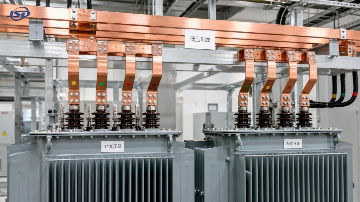
Parallel operation of a three phase power transformer can increase available capacity without replacing an existing unit, keep critical loads supplied during maintenance, and provide a practical path for phased expansion. In substations, factories, renewable plants, and large commercial facilities, this arrangement is often more flexible than installing one very large transformer.
It is not, however, a matter of closing a tie breaker between two transformers with similar nameplate ratings. A parallel connection is feasible only when the transformers produce secondary voltages that are effectively identical in magnitude, phase angle, and phase sequence, and when their impedances allow load to divide within safe limits. If those conditions are not met, the result can be persistent circulating current, overloaded windings, nuisance protection trips, excessive neutral current, or a severe fault at the instant of energization.
The practical question is therefore not whether two transformers can be connected in parallel, but whether they can remain connected safely across the expected range of load, tap positions, operating temperatures, and network configurations.
The conditions that make parallel operation feasible
Two transformers connected to the same primary source and the same secondary bus must be electrically compatible. Brand, manufacturing year, cooling medium, and physical size do not by themselves determine compatibility. A modern dry-type unit can sometimes operate in parallel with an oil-immersed unit, for example, but only after the electrical conditions have been verified through drawings, nameplates, test reports, and site measurements.
The essential conditions are closely related. A mismatch in any one area may be manageable only if a qualified power-system study demonstrates that the resulting current and thermal duty remain acceptable.
Voltage ratio: the no-load check that cannot be skipped
The most basic requirement is an equal effective turns ratio. If one transformer has a slightly higher secondary voltage than the other, it will drive current into the lower-voltage transformer. This circulating current does not serve the load. It consumes transformer capacity and causes additional copper losses and heating.
The issue becomes more important when the transformers are large and the secondary bus is stiff. A seemingly minor voltage difference may create a significant current because transformer leakage impedance is intentionally low. Nameplate primary and secondary voltage ratings must therefore be compared on the actual operating tap, not merely at nominal tap.
For transformers with off-circuit tap links, all changes should be performed de-energized and confirmed against the manufacturer’s diagram. For on-load tap changers, the control logic requires particular care. Two units operating in parallel should not independently chase voltage without coordination. Their automatic voltage-regulation scheme must be designed for parallel operation, commonly using master-follower, circulating-current compensation, or another approved control method.
One recurring field error is assuming that the same tap position number means the same secondary voltage. That is not guaranteed when units have different nominal ratios, tap ranges, or tap-step increments. The relevant value is the resulting ratio and secondary voltage, not the marking on the selector handle.
Vector group compatibility is a hard boundary
Vector group identifies winding connections and the phase displacement between high-voltage and low-voltage windings. A Dyn11 transformer, for example, has a different phase relationship from a Dyn1 transformer. Even if both nameplates show the same voltage ratio and kVA rating, their secondary voltages are separated by a phase-angle difference. Directly paralleling them on the same low-voltage bus is generally not possible.
Transformers may be suitable for parallel service when their vector groups are identical. In some cases, different vector designations can be made compatible through carefully designed external phase transposition, but this is an engineering exercise rather than a field adjustment. It should never be attempted by changing cables based only on assumptions about terminal labels.
Phase sequence is equally important. Before a new transformer is tied to an energized bus, site personnel should confirm the sequence using an approved phase-sequence indicator or voltage test method and verify the actual terminal identification against the approved connection drawing. A correct vector group on paper does not protect the installation from a wiring error made during commissioning.
Impedance determines whether capacity is actually shared
Once voltage magnitude and phase alignment are correct, impedance becomes the main determinant of load division. Every transformer has a percentage impedance, often shown as impedance voltage or %Z on its nameplate. Under parallel operation, the unit with lower impedance tends to carry more current.
For transformers on the same voltage bus with broadly similar impedance angle, load sharing is approximately proportional to each transformer’s rated capacity divided by its percentage impedance. In simplified form:
Load share of each transformer ∝ rated kVA ÷ % impedance.
That relationship explains why identical kVA ratings do not necessarily mean a 50/50 load split. If two 2 MVA transformers have materially different impedance values, the lower-impedance unit may reach its thermal limit while the combined bus load appears to be below the combined 4 MVA rating.
Percentage impedance alone is not the full story. The impedance angle, often represented through the X/R ratio, also affects real and reactive power sharing. Differences are more visible where loads have poor power factor, where large motors start frequently, or where power-electronic equipment creates rapidly changing reactive-power demand. An engineering review should also assess prospective short-circuit current, because adding a parallel transformer lowers the equivalent source impedance and can increase fault duty beyond the interrupting rating of switchgear or breakers.
A useful operating rule is to treat the lower-rated transformer as the limiting unit until actual load-sharing measurements confirm otherwise. Do not calculate available capacity by simply adding nameplate ratings unless the impedance study supports that assumption.
Grounding and zero-sequence behavior matter more than many installations expect
Parallel transformers do not only share balanced three-phase load. They also respond to unbalanced load, line-to-ground faults, harmonic currents, and neutral current. The winding connection and grounding method determine the path available to zero-sequence current.
For example, a grounded-wye secondary may provide a source for ground-fault current, while a delta winding can contain certain triplen harmonic components and zero-sequence currents within the delta loop. If parallel units have different neutral grounding arrangements, one transformer may carry a disproportionate share of earth-fault or neutral current. This can affect relay sensitivity, ground-fault selectivity, and the thermal duty of neutral conductors and grounding resistors.
When an installation has a common neutral bus, neutral grounding resistors, or multiple transformer neutrals connected to the same earth grid, the grounding design should be reviewed as part of the parallel scheme—not after commissioning. Protection settings that worked with one transformer may no longer be selective when a second source is added.
Where parallel operation provides a sound application solution
Parallel operation is particularly useful where the load grows in stages or where a single transformer outage is unacceptable. A manufacturing plant may install one unit for current demand and add a second when a new production line is commissioned. A data-intensive facility may use two transformers to retain partial service during planned maintenance. Renewable-energy and battery projects may require several medium-voltage transformer blocks to accommodate modular inverter or storage capacity.
In energy storage applications, the transformer interface deserves the same scrutiny as the battery container itself. A project using a 1MW/2MWh Liquid Cooling Container Energy Storage System may expand by adding further conversion and storage blocks. If these blocks connect through separate transformers to a common medium-voltage collector bus, engineers must assess transformer vector groups, impedance, grounding, relay coordination, and export-control behavior together. Battery systems can move rapidly between charging and discharging, so a poor parallel design may reveal itself as fluctuating current sharing rather than as a steady overload.
In this type of installation, the energy management system, power conversion controls, and transformer tap strategy should be coordinated. A transformer arrangement that is technically acceptable at rated discharge may behave differently during low-load charging, reactive-power support, or islanded microgrid operation.
A commissioning sequence that reduces avoidable risk
Safe parallel operation starts before the tie breaker is closed. The following actions form a practical field sequence, although site procedures and local electrical safety rules always take priority.
- Review nameplates, factory routine-test records, wiring diagrams, impedance data, vector groups, tap ranges, cooling ratings, and neutral arrangements.
- Confirm that rated frequency, primary supply voltage, secondary voltage, and insulation levels fit the installed network.
- Verify all tap positions and ensure automatic tap-control functions are blocked or placed in the approved manual state during the initial check.
- Perform insulation, winding-resistance, ratio, vector-group, and polarity tests as required by the commissioning plan.
- Check phase sequence and measure voltage between corresponding terminals of the open tie point. The expected differential voltage should be within the approved commissioning limit.
- Review protection coordination, including differential protection, overcurrent, earth-fault elements, restricted earth-fault functions where installed, and breaker fault-duty ratings.
- Close the parallel tie under controlled conditions, preferably at low load, and record each transformer’s current, kW, kVAr, voltage, neutral current, and temperature.
- Increase load gradually while monitoring current balance and confirming that no unit exceeds its applicable winding, oil, or hotspot temperature limits.
Measurements should not end after the first successful closure. Load sharing can change with tap movement, cooling-stage changes, power-factor variation, seasonal temperature, or altered feeder configuration. Trending secondary currents and kVAr contribution is more informative than occasional spot checks, especially where unequal transformer sizes are used.
Situations where transformers should not be paralleled without redesign
Some conditions are clear warning signs. Transformers with different phase displacement should not be tied directly to the same secondary bus. Units with significantly unequal ratios, incompatible tap ranges, or unknown test history should not be treated as compatible merely because both are described as three-phase transformers. A transformer showing abnormal gas generation, insulation deterioration, moisture concerns, or unresolved protection trips should be investigated independently before it is placed in a shared load arrangement.
It is also risky to parallel a replacement transformer solely because its kVA rating is close to that of the original. The new unit may have a different impedance, vector group, terminal arrangement, or grounding philosophy. In brownfield sites, documentation can be incomplete and cable phasing may not match drawings after years of modifications. Field verification is therefore a technical necessity, not administrative formality.
Parallel operation is feasible when the transformers act electrically as compatible sources rather than competing voltage sources. Equal effective ratio, correct vector relationship and phase sequence, suitable impedance matching, coordinated taps, and a reviewed grounding and protection design are the core requirements. When those conditions are verified, parallel transformers can provide a resilient and scalable power solution. When they are assumed rather than demonstrated, the same arrangement can turn routine switching into a serious system event.

Get a Quote
Regardless of whether you require general advice or specific support, we are happy to help you.
Send Us Your Inquiry Today

Jinshida Electric remains committed to contributing to global energy development through professional manufacturing and superior service.