





How to diagnose voltage imbalance in a three phase transformer
Voltage imbalance in a three phase transformer can lead to overheating, reduced efficiency, insulation stress, and unexpected equipment failures. Early diagnosis is essential to protecting transformer performance and ensuring stable power delivery. The practical challenge is not merely identifying an unequal voltage reading: it is determining whether the condition originates upstream, inside the transformer, in the secondary circuit, or from an unbalanced connected load.
A reliable diagnosis requires measurements taken at the right locations, under known operating conditions, and interpreted together with current, temperature, tap position, and connection data. A single voltage reading can reveal a symptom; it rarely proves the cause.
What counts as voltage imbalance?
In a balanced three-phase system, the three phase-to-phase voltages should be close in magnitude and displaced by 120 electrical degrees. In a four-wire secondary system, phase-to-neutral voltages should also be similar. Small differences occur in real installations, but a persistent deviation deserves investigation before it develops into a thermal or insulation problem.
A commonly used calculation is:
Voltage imbalance (%) = Maximum deviation from average voltage ÷ Average voltage × 100
For example, if measured line voltages are 402 V, 398 V, and 390 V, the average is 396.7 V. The greatest deviation is 6.7 V, so the voltage imbalance is approximately 1.7%.
This calculation is useful for trend monitoring, but it should not be used in isolation. The significance of a 1% imbalance differs between a lightly loaded distribution transformer and a heavily loaded unit feeding variable-speed drives, rectifier loads, welding equipment, or a large motor group. Voltage imbalance also produces a disproportionate effect on induction motors, where relatively modest voltage asymmetry can create substantially greater current imbalance and heating.
Start with safe, comparable measurements
Before opening a transformer enclosure or connecting test equipment, establish the operating state. Record the transformer nameplate rating, vector group, rated primary and secondary voltages, tap-changer type, present tap position, neutral grounding arrangement, and approximate load level. Confirm lockout and access procedures where de-energized work is required. For energized checks, use correctly rated instruments and follow the applicable site safety rules.
The most useful initial readings are:
- Primary line-to-line voltages at the transformer incoming terminals;
- Secondary line-to-line voltages at the transformer outgoing terminals;
- Secondary line-to-neutral voltages where a neutral is available;
- Phase currents on all three phases and neutral current where applicable;
- Transformer load percentage, ambient temperature, and time of measurement;
- Tap position and any automatic voltage regulator status.
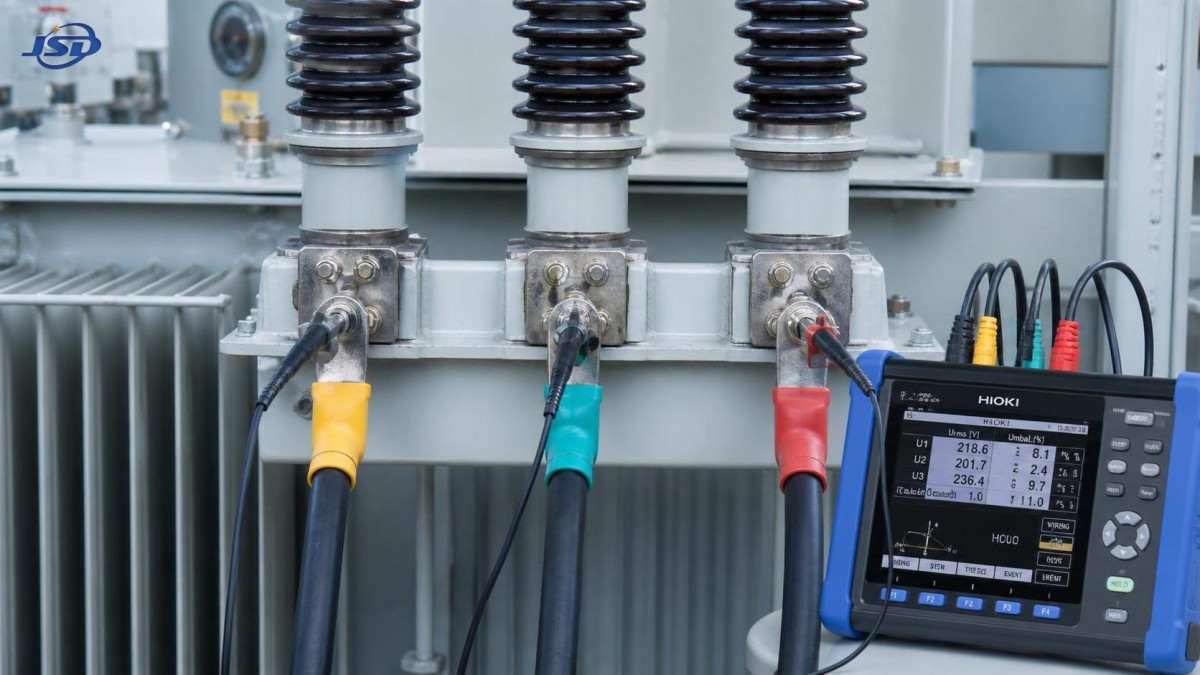
Use a true-RMS power quality analyzer or calibrated three-phase meter where nonlinear loads are present. A basic handheld meter may provide acceptable steady-state voltage values, but it can miss waveform distortion, voltage events, harmonic content, and phase-angle information that explain apparently inconsistent results.
Readings should ideally be captured under at least two conditions: normal operating load and a reduced-load period. If the imbalance increases with load, the fault is more likely related to load distribution, high-resistance connections, secondary conductors, or transformer winding impedance. If it remains almost unchanged regardless of load, the primary supply, transformer ratio, tap setting, or a fixed wiring issue becomes more likely.
Use measurement location to separate supply-side and transformer-side faults
The fastest diagnostic distinction is between an imbalance already present at the primary terminals and one that appears only after transformation.
If primary voltage is unbalanced and secondary voltage follows the same pattern: the source is usually upstream. Possible causes include unequal feeder impedance, poor connections at an upstream switchgear terminal, an unbalanced utility supply, a faulty regulator, or unequal loading on the upstream network. The transformer may be affected by the condition, but it is not necessarily the origin.
If primary voltages are balanced but secondary line voltages are unbalanced: focus on the transformer, tap arrangement, secondary bushings, cable terminations, or downstream conductors. Confirm that measurements are taken directly at transformer terminals before attributing the issue to winding damage. A loose secondary lug, overheated cable joint, corroded bushing contact, or damaged breaker pole can create a significant voltage drop under load.
If secondary terminal voltages are balanced but load-end voltages are unbalanced: the transformer is generally not the cause. Investigate the outgoing feeder, distribution board, busbar joints, contactors, circuit breakers, cable sizing, and load-side neutral condition. Measure voltage drop phase by phase between the transformer and the affected equipment.
If line-to-line voltages appear acceptable but phase-to-neutral voltages differ materially: examine the neutral conductor and neutral-to-earth arrangement. A loose, undersized, damaged, or floating neutral can shift phase-to-neutral voltages dramatically in a four-wire system, particularly where single-phase loads are unevenly distributed. This condition can damage connected single-phase equipment even when line-to-line readings appear normal.
Compare voltage imbalance with current imbalance
Voltage and current must be assessed together. Their relationship often points to the likely fault category.
Do not assume that the phase with the lowest measured voltage is necessarily the phase with the lowest load. A high-resistance connection can cause a loaded phase to show lower voltage precisely because it is carrying significant current through a deteriorated joint. Infrared inspection is especially valuable in this case, as it can reveal abnormal heating at bushings, cable lugs, isolators, breaker contacts, and busbar interfaces.
Inspect common causes in a practical order
Once the measurement pattern is established, proceed from external and reversible causes toward internal transformer defects. This order reduces unnecessary outages and avoids prematurely condemning a transformer.
Load distribution and downstream circuit condition
In commercial and industrial installations, single-phase loads often accumulate unevenly as circuits are added over time. Lighting, HVAC auxiliaries, office loads, chargers, welding machines, and small process equipment may be concentrated on one phase. Check panel schedules against actual measured branch currents rather than relying on drawings alone.
Nonlinear loads require separate attention. Switch-mode power supplies, UPS systems, LED drivers, rectifiers, and variable-frequency drives can introduce harmonics that increase neutral current and heating. Harmonic distortion does not always create fundamental-frequency voltage imbalance, but it can distort meter readings and aggravate a weak neutral or overloaded conductor.
Loose, corroded, or overheated connections
Connections are among the most frequent causes of field voltage imbalance. Look for discoloration, melted insulation, carbon tracking, oxidized aluminum interfaces, inadequate bolt torque, damaged lugs, and evidence of moisture ingress. A connection may look acceptable when de-energized yet develop excessive voltage drop only under current.
Thermal scanning should be performed under meaningful load whenever possible. Compare like-for-like components across all phases: similar bushings, cable lugs, breaker poles, and busbar joints should have comparable temperature rise under comparable current. A temperature difference is an indicator, not final proof; confirm it with torque checks, resistance testing, and voltage-drop measurements.
Tap setting and tap-changer condition
A wrong manual tap position can produce an overall voltage level error, but it does not normally create unequal phase voltages in a healthy three-phase transformer. However, contact deterioration, mechanical misalignment, or a defective tap-changer component can affect one phase differently, depending on transformer design.
Check that the indicated tap position matches the intended system voltage and that all phases are operating on the same effective tap. For on-load tap changers, review operation counters, alarms, motor-drive status, oil condition where applicable, and any recorded abnormal transition events. Do not operate tap equipment repeatedly to “test” it without following the manufacturer’s procedure; unnecessary operations can worsen an existing contact problem.
Transformer winding, bushing, or internal connection faults
Internal faults are less common than external connection or load problems, but they must be considered when the imbalance is confirmed at transformer terminals and cannot be explained by supply conditions or tap settings. Potential causes include shorted turns, poor internal joints, winding deformation, bushing deterioration, or localized insulation damage.
Relevant offline tests may include winding resistance measurement, transformer turns ratio testing, excitation current testing, insulation resistance and polarization index testing, and, where justified, frequency response analysis. Test selection should reflect transformer type, fault history, age, prior test baselines, and observed symptoms. A single abnormal result should be evaluated against test method limits and historical records before concluding that winding replacement is necessary.
Special considerations where energy storage is connected
Three-phase transformer imbalance is increasingly encountered at sites combining conventional loads with photovoltaic generation, battery systems, and bidirectional power conversion equipment. The operating pattern can change rapidly between charging, discharging, standby, and islanded modes. Measurements taken during one mode may not represent the condition during another.
For example, a containerized system such as the 500kW/1MWh Air Cooling Container Energy Storage System provides 400 V three-phase four-wire AC output through a 500 kW power conversion system. At an installation using this type of equipment, verify phase-voltage balance both at the PCS output and at the transformer terminals during charge and discharge. Review controller event logs, power setpoints, phase-current data, protection records, and communication status before treating a temporary imbalance as a transformer defect.
In parallel operating arrangements, confirm transformer vector group compatibility, grounding method, phase sequence, cable impedance, and control coordination. A transformer issue can be masked during one operating mode and become obvious when the battery system changes power direction. Conversely, a converter control alarm, current sensor issue, or feeder problem can be mistaken for a transformer fault if the test point is poorly chosen.
Do not overlook instrument and connection errors
Incorrect diagnosis often begins with incorrect measurements. Verify meter leads, phase identification, probe contact quality, clamp orientation, voltage rating, and instrument calibration status. When using a power quality analyzer, confirm the wiring configuration in the instrument setup: three-wire delta, four-wire wye, and Aron configurations require different connections and assumptions.
Repeat suspicious measurements with a second instrument or at a nearby verified point. If phase sequence appears abnormal after recent work, check for swapped conductors before investigating more complex causes. A phase-labeling error can create misleading maintenance records and lead to the wrong feeder being isolated.
When voltage imbalance requires urgent action
Immediate escalation is appropriate when voltage imbalance is accompanied by burning odor, smoke, visible arcing, rapidly increasing temperature, relay alarms, oil leaks, repeated protective trips, abnormal sound, or a sharp change from prior baseline readings. Reduce load or isolate equipment according to the site operating procedure where continued operation risks equipment damage or personnel safety.
Even without dramatic symptoms, trend deterioration matters. A transformer that has operated with stable voltage for years and develops a growing phase deviation should not be left until the next routine shutdown. Capture readings at similar load levels, compare them with earlier records, and inspect the highest-probability external causes promptly.
Build a record that supports the next decision
A useful service record includes date and time, weather or ambient conditions, transformer identification, tap position, load estimate, voltage and current values for every phase, neutral current, measurement location, instrument used, thermal findings, alarm history, and corrective action taken. Add photographs of suspect connections and preserve analyzer trend files when available.
This documentation is not administrative excess. It makes it possible to distinguish a recurring network-quality issue from a developing transformer defect, verify whether load balancing improved the condition, and provide credible evidence if warranty, utility coordination, or engineering review becomes necessary.
The most dependable approach to diagnosing voltage imbalance in a three phase transformer is therefore sequential: confirm the measurement, locate where the imbalance first appears, compare voltage with current and temperature, rule out load and connection problems, then test taps and internal transformer components when evidence supports that step. This method limits unnecessary transformer intervention while addressing the faults most likely to compromise reliable power delivery.

Get a Quote
Regardless of whether you require general advice or specific support, we are happy to help you.
Send Us Your Inquiry Today

Jinshida Electric remains committed to contributing to global energy development through professional manufacturing and superior service.