





How to locate the source of an oil leak on a 500 kVA transformer
How to locate the source of an oil leak on a 500 kVA transformer
An oil stain beneath a 500 kVA transformer does not always reveal where the leak began. Oil can travel along tank surfaces, making a leaking bushing gasket, radiator joint, or drain valve difficult to pinpoint. Tracing the source accurately helps prevent repeat repairs, unnecessary oil loss, and potential insulation problems. The most useful approach is to preserve the initial evidence, trace the highest fresh oil mark, then clean and observe small areas until the actual escape point becomes clear.
Before cleaning surfaces or examining components closely, follow site procedures for isolation, lockout/tagout, verification of absence of voltage, and grounding where required. Transformer capacity alone does not determine the inspection method: tank construction, cooling arrangement, oil preservation system, and manufacturer instructions matter more.
Decide whether fault-finding can wait
Start with observations from outside the applicable electrical approach boundary. A dusty, oily patch is different from an active stream. Neither should be ignored, but a rapidly falling oil level, protective-device operation, smoke, abnormal noise, or oil near live connections requires immediate escalation under the site emergency procedure—not a closer look with a cloth.
Check the indicated oil level against the manufacturer’s temperature-related guidance, where provided. A reading without oil temperature can be misleading. If the level is below the permitted operating range, do not assume that topping up makes continued operation acceptable. The cause, possible air entry, and insulation condition need assessment.
Contain spilled oil using approved materials and protect nearby drains. Do not loosen a plug, valve, cover, or bushing fitting to “see whether it is tight.” A de-energized transformer may still contain hot oil and internal pressure. Electrical isolation does not establish that the tank is safe to open.
Record the evidence before wiping it away
Photograph the whole transformer, then each wet area with enough surrounding detail to identify its location. Record load, indicated oil temperature, ambient conditions, oil level, and whether leakage appeared after transport, maintenance, or a load change. These details help distinguish a persistent seal failure from old filling residue or an intermittent leak.
A useful inspection note describes what actually happened: “fresh bead formed beneath the lower radiator flange during observation,” rather than simply “radiator leaking.” Record the observation period as well. A dark stain may remain long after leakage has stopped; fresh wetting is stronger evidence.
Consider other liquids without touching or smelling an unknown substance. Rainwater mixed with dirt, lubricant from nearby equipment, and oil left after servicing can confuse the picture. Review recent work records and use approved identification methods where necessary. On older equipment, confirm any applicable oil-handling restrictions before cleanup or sampling.
Trace the oil uphill, including sideways
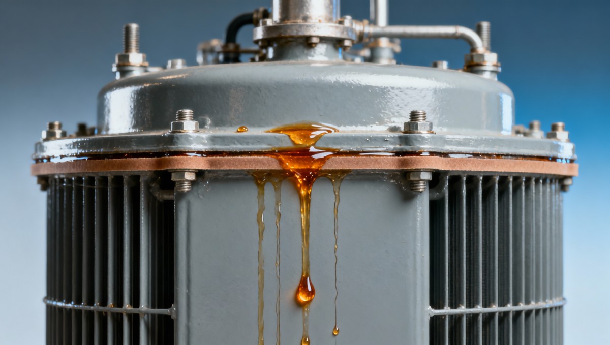
The lowest wet point is usually a collection point, not reliable proof of origin. Start there and work upward, checking seams, folded edges, brackets, bolt heads, and radiator connections. Oil follows gravity, but surface tension and narrow gaps can carry it sideways before it drops.
For example, a bushing-base leak can spread across the cover, reach a corner, and run down behind a radiator. The bottom radiator connection may then look responsible. Before disturbing that joint, inspect the cover above it and the concealed surfaces behind it. A mirror or inspection camera can help once access is electrically and mechanically safe.
Look for the transition from dry material to fresh wetting. This narrows the search, but does not prove the source: oil can emerge from beneath a bracket after travelling from another location.
Clean small sections and watch where oil returns
After documenting the original condition, clean accessible suspect areas with lint-free materials and a manufacturer-approved cleaner compatible with paint, seals, and insulating surfaces. Avoid pressure washing or indiscriminate solvent spraying. These can spread contamination, damage materials, or erase the trace you need.
Dry the surface and observe one joint at a time. A fresh bead forming directly at a gasket edge is more persuasive than an oily flange underside. Where permitted, use a clean absorbent witness strip beneath a suspect external joint, clear of terminals, hot surfaces, and moving equipment. Remove temporary materials before return to service.
Some leaks become visible quickly; others depend on temperature and tank pressure. No fresh oil during a short cold inspection does not establish that the seal is sound. Never re-energize equipment simply to provoke leakage without an approved assessment and operating plan.
Check the likely sealing points against the transformer design
Bushing bases and cover joints
Inspect around each bushing mounting interface, especially hidden edges where oil can collect. Separate leakage at the tank-to-bushing gasket from leakage through the bushing assembly itself. Cracked insulation, tracking, or a damaged terminal assembly calls for specialist assessment; tightening mounting hardware is not a substitute.
At a bolted cover, inspect corners and changes in flange geometry. A continuous oily line can originate at one failed section and spread along the gasket. Uneven compression, gasket deterioration, or flange distortion are possible causes, but appearance alone cannot tell you which one applies.
Radiators, cooling panels, and welded seams
On units with detachable radiators, distinguish a flange-gasket leak from a leaking valve, tube, or welded joint. With corrugated tanks, examine panel folds and weld transitions for localized fresh wetting. A fine defect can leave a narrow trail rather than an obvious drop.
Oil emerging repeatedly through a cleaned painted surface may indicate a defect beneath the coating. Do not scrape aggressively or attempt field welding on an oil-containing tank. Tank repairs require a specialist procedure addressing oil handling, fire hazards, structural integrity, and post-repair testing.
Valves, instruments, and operating mechanisms
Drain valves and sampling fittings are easy to blame because they sit low. Check above them before deciding. If fresh oil returns at the valve body-to-tank connection, that is a different fault from leakage through the valve outlet or around its stem. A cap may conceal seat leakage rather than cure it.
Also inspect oil-level indicators, thermometer pockets, pressure-relief device mountings, and external tap-changer operating shafts where fitted. Oil near a pressure-relief device requires particular care: gasket seepage and evidence of device operation have different implications. Do not block the outlet or interfere with its protective function.
When a cold inspection finds nothing
An intermittent transformer oil leak may follow thermal expansion, changes in oil head, or pressure variation. Compare the inspection conditions with the conditions when the stain appeared. A leak seen after a high-load period may stop after shutdown and cooling, even though the defect remains.
The preservation system matters. A sealed tank and a conservator-equipped transformer do not respond identically to temperature changes. Check the specific drawings and operating instructions rather than applying a generic pressure assumption to every 500 kVA transformer.
If visual tracing remains inconclusive, ask the manufacturer about an approved leak test. Do not improvise with compressed air, oxygen, vacuum, or an arbitrary test pressure. Permissible methods and limits depend on tank construction and fitted accessories. Likewise, fluorescent dyes and external detection products should not be introduced without explicit compatibility approval.
At sites with solar or backup supplies, include every possible backfeed source in the isolation plan. A 51.2V Wall-mounted LiFePO4 Energy Storage Battery may support selected loads through a compatible inverter, but it is not a replacement for a 500 kVA transformer supply. Its presence makes verified source isolation more important; it does not make transformer inspection safe by itself.
Confirm the source before choosing the repair
A credible diagnosis identifies the exact interface, shows fresh leakage after cleaning, and explains how oil reached the visible stain. If one of those elements is missing, the diagnosis may still be provisional. Two leaks can also exist at once, particularly where several seals have aged under similar conditions.
Avoid the common shortcut of tightening every accessible bolt. Excess torque can damage bushings, distort flanges, or extrude gaskets. Use the specified gasket material, tightening sequence, and torque for that assembly. Some repairs require controlled oil lowering or component removal; decide this before disturbing the joint.
For equipment supplied by Jinshida Electric Power Technology Co., Ltd., a useful technical-support request includes the nameplate, serial number, overall photographs, close-ups of the confirmed escape point, operating conditions, and maintenance history. This gives the manufacturer’s technical team a practical basis for checking the sealing arrangement and repair requirements.
Before return to service, verify oil level, accessory positions, cleanliness, and any required post-repair checks under the approved procedure. Whether oil testing is needed depends on oil loss, exposure to air or moisture, and the work performed. Inspect the repaired area again after the next authorized operating cycle. A dry surface immediately after wiping is not proof of a successful repair; a joint that remains dry under the relevant operating conditions is much stronger evidence.

Get a Quote
Regardless of whether you require general advice or specific support, we are happy to help you.
Send Us Your Inquiry Today

Jinshida Electric remains committed to contributing to global energy development through professional manufacturing and superior service.