





When does a three phase distribution transformer need a neutral point?
A three phase distribution transformer needs a neutral point when the low-voltage system must serve line-to-neutral loads, establish a defined grounding reference, or allow protective devices to detect and clear earth faults reliably. It is not an automatic requirement for every three-phase installation. The correct decision depends on the transformer winding connection, the types of connected loads, the earthing arrangement, and the applicable local electrical code.
The practical question is rarely “Does a transformer have a neutral?” A more useful question is: “What must the secondary distribution system do after the transformer?” A 400/230 V building supply, for example, normally requires a neutral conductor. A motor-only 400 V process line may not. Confusing these two cases can lead to the wrong transformer vector group, an ineffective protection scheme, or expensive changes after commissioning.
What the neutral point actually does
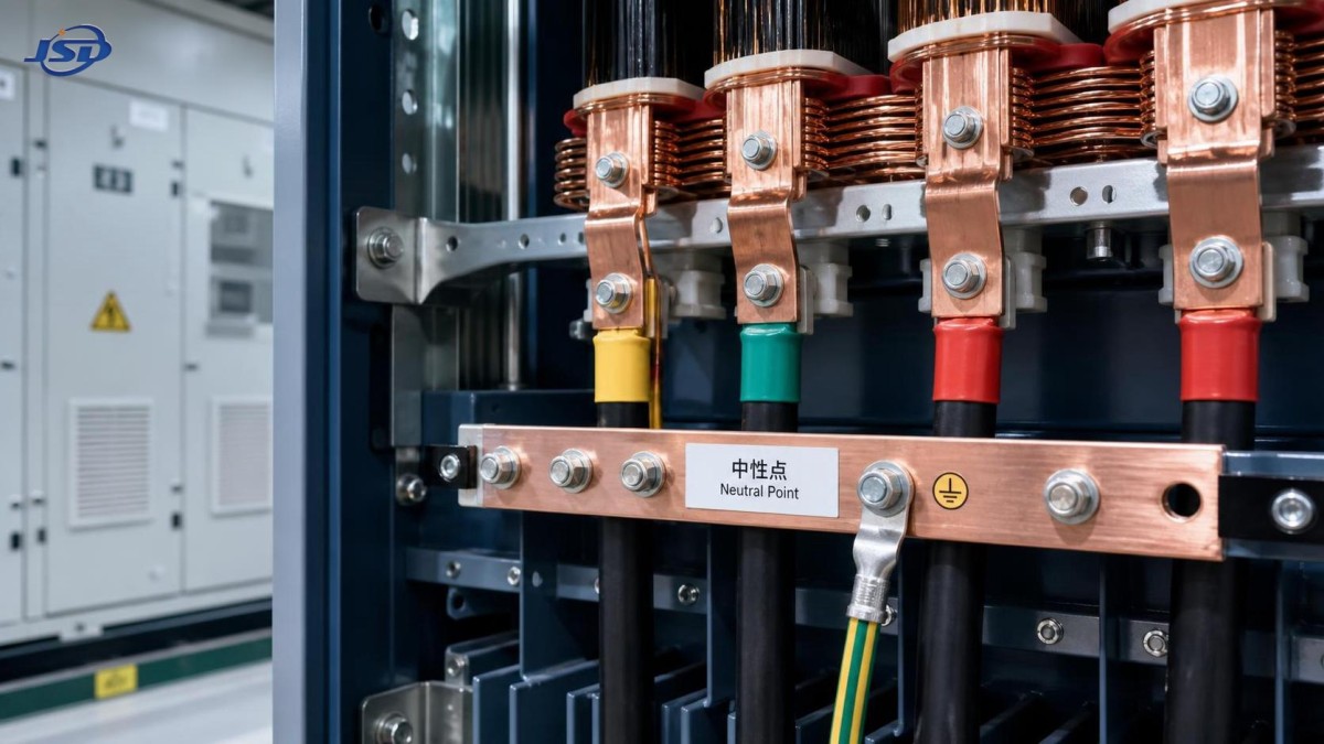
In a three-phase four-wire system, the neutral is the common reference point for the three phase voltages. It is usually derived from a star-connected secondary winding. For a 400/230 V system, each phase-to-neutral circuit supplies approximately 230 V, while each phase-to-phase circuit supplies 400 V.
The neutral serves three separate purposes that are often mixed together:
- It supplies single-phase loads connected from phase to neutral.
- It provides a reference point for the low-voltage system voltage.
- When intentionally earthed, it supports earth-fault detection and a controlled fault-current path.
These functions are related, but they are not identical. A system may have a star point internally yet not distribute a neutral conductor. It may also have a neutral conductor that is connected to earth at a defined location under a TN arrangement. The project drawings and protection philosophy need to state both points clearly.
In simple terms: a neutral point is needed when the installation needs a stable phase-to-earth and phase-to-neutral reference, not merely because there are three phases available.
When a three phase distribution transformer needs a neutral point
The most common case is a mixed low-voltage distribution board. Offices, retail sites, public facilities, residential feeders, hospitals, and many commercial buildings contain lighting, sockets, controls, IT equipment, small UPS units, and single-phase HVAC auxiliaries. These loads are normally spread across L1, L2, and L3 and connected back to neutral. A star-connected low-voltage winding with an accessible neutral is therefore the normal arrangement.
A neutral is also usually required where the earthing system relies on a solidly earthed transformer star point. In a TN system, bonding the neutral point to the earthing arrangement at the source creates a predictable path for a line-to-earth fault. That path helps protective devices operate within the disconnection times required by the applicable installation rules. The exact arrangement, whether TN-S, TN-C-S, TT, or IT, must be selected against the governing standard and utility requirements rather than assumed from transformer nameplate voltage alone.
Another case is a network with significant unbalanced loading. Perfect phase balance is unusual outside dedicated motor systems. Lighting groups, socket circuits, single-phase chargers, and electronic loads move the phase currents apart. The neutral carries the imbalance current. Without a neutral, those loads cannot be supplied in the intended way, and attempts to create an artificial reference can produce unstable voltages.
There is a further issue in installations with high levels of nonlinear load. Switch-mode power supplies, variable-speed drives, LED lighting, and data equipment can produce triplen harmonics, particularly third-order components. In a four-wire system, these harmonic currents can add in the neutral instead of cancelling. This does not mean every installation needs an oversized neutral, but it does mean neutral conductor sizing and harmonic assessment should be part of the design review.
Cases where a neutral may not be necessary
A three-wire secondary can be appropriate when all downstream loads are phase-to-phase. A dedicated pumping station with only three-phase induction motors, motor starters, and line-to-line control transformers may operate well without a distributed neutral. The same can apply to a closed industrial feeder serving balanced three-phase heating equipment.
Delta-connected secondary systems are often used in these circumstances. They have no natural neutral point available for four-wire supply. This can be a sound engineering choice, particularly where continuity under certain winding faults or the containment of triplen harmonics is relevant. It is not, however, a shortcut for avoiding grounding design. A delta system still needs a deliberate earthing and fault-protection strategy.
Do not reject a neutral simply because the present load list contains only motors. Distribution systems tend to change. A future PLC panel, temporary construction supply, security lighting, instrumentation power supply, or office extension can quickly turn a three-wire installation into a four-wire requirement. If that expansion is reasonably foreseeable, providing a suitable neutral point at the transformer can avoid a disruptive replacement later.
Start with the secondary load schedule, not the transformer rating
A transformer may have enough kVA capacity and still be the wrong choice if its secondary connection does not match the distribution architecture. Before approving a three phase distribution transformer, review the actual circuits that will be fed from the main low-voltage board.
Look beyond connected kW. Identify phase-to-neutral circuits, expected load diversity, the proportion of electronic loads, future spare ways, and the fault-clearing method. Also confirm whether the quoted 400 V is a line-to-line value, because this is a frequent source of confusion. A 400 V line-to-line system is commonly paired with about 230 V line-to-neutral, but the permitted nominal voltages and tolerances must follow the project specification and local standards.
The winding connection determines what is available
A star winding provides a physical neutral point. A delta winding does not. For many distribution duties, a delta primary and star secondary arrangement is selected because it gives a usable low-voltage neutral while isolating some zero-sequence and triplen harmonic effects from the upstream network. The vector group must still be checked against parallel operation requirements, phase displacement, protection coordination, and the utility’s connection conditions.
It is not enough to request “Dyn” or “star secondary” on a purchase order. Confirm whether the neutral is brought out through a bushing, whether it is rated for the intended service, how it will be earthed, and whether the transformer design supports the expected fault duty. Neutral earthing equipment, if specified, is part of the system design rather than an afterthought.
For a 15 kV to 0.4 kV project serving urban distribution, commercial loads, or an industrial plant with mixed auxiliaries, the secondary neutral should be defined in the single-line diagram before equipment selection. An option such as the 15kV/0.4kV Oil-Immersed Power Distribution Transformer is relevant where the project needs that voltage conversion and a distribution configuration suited to the downstream load profile. Its stated 30-5000 kVA range covers very different applications, so the neutral arrangement, vector group, loss requirements, cooling conditions, and protection interfaces still need project-specific confirmation.
For sites where environmental considerations affect equipment selection, FR3 vegetable oil may be an available option. That decision should be evaluated separately from the neutral question. Fluid choice can affect fire-safety and environmental planning; it does not determine whether the low-voltage network requires a four-wire secondary.
Grounding is the point where many designs go wrong
A neutral conductor is not the same thing as a protective earth conductor. They may be connected at a defined source point in some earthing systems, but they serve different functions downstream. Using a neutral as a casual substitute for protective earth creates both safety and compliance risks.
The required earth-fault loop impedance, prospective fault current, protective-device curves, and disconnection times must be verified as a system. A solidly earthed neutral can provide high fault current and fast operation of overcurrent protection. A resistance-earthed or isolated system behaves differently and may require insulation monitoring or sensitive earth-fault relays. Neither approach is universally better; each is chosen for a specific operating and safety objective.
One common mistake is to assume that a low-impedance neutral-to-earth connection is always preferable. In a process facility, high earth-fault current can cause extensive damage or unnecessary shutdowns. In another installation, insufficient fault current can prevent a conventional breaker from operating quickly enough. The protection study decides the answer.
Neutral loading and voltage stability deserve separate checks
When phase-to-neutral loads are materially unbalanced, the neutral current can become substantial. The resulting voltage drop is not merely a conductor issue. It can affect single-phase equipment performance, nuisance alarms, contactor operation, and sensitive electronics. Balancing circuits across phases remains the first practical control measure.
Nonlinear loads require a closer look. Harmonic current may heat the neutral and transformer windings even when phase current readings appear acceptable. A load survey or harmonic study is appropriate where the site contains concentrated IT loads, large LED installations, rectifier systems, or certain drive applications. Do not apply a generic derating factor without measurement or a defensible load model.
Neutral current transformers, residual-current protection, and metering arrangements must also match the chosen earthing system. A neutral conductor that is omitted from the original design cannot be added casually later without revisiting these devices and their settings.
A practical approval checklist
Before finalizing the transformer specification, confirm these questions with the electrical designer, installer, and network owner where applicable:
- Are any present or planned loads rated phase-to-neutral?
- Which earthing system is required at the transformer secondary?
- Is the low-voltage winding star-connected, and is its neutral brought out?
- What line-to-earth fault current is expected, and how will protection clear it?
- Are substantial nonlinear loads likely to create neutral harmonic current?
- Will the transformer operate in parallel with another unit, requiring compatible vector groups and earthing arrangements?
- Do the utility, local authority, and governing installation standard impose a specific neutral or grounding method?
These questions are more valuable than relying on a generic “three-phase transformer” description. They expose whether the neutral is a true operating requirement, a protection requirement, a future-proofing decision, or unnecessary for the defined load.
Questions that come up during specification
Can a star-connected transformer operate without distributing a neutral?
Yes. The star point may exist but remain unused as a load conductor. Whether it is earthed, accessible, or required for protection depends on the system design.
Does every 400 V transformer need a neutral?
No. A 400 V three-wire supply can serve phase-to-phase loads. A 400/230 V four-wire supply needs a neutral when 230 V loads are part of the installation.
Can the neutral be undersized because loads are balanced?
Only after a proper assessment. Load imbalance, future changes, and triplen harmonic currents can make a reduced neutral unsuitable.
Is the transformer neutral automatically safe to earth anywhere?
No. The location and method of neutral earthing must follow the selected earthing arrangement and protection design. Multiple unintended neutral-earth bonds can create circulating current and protection problems.
The decision in one sentence
Select a three phase distribution transformer with an accessible, properly earthed neutral point when the secondary system needs phase-to-neutral supply, a defined ground reference, or earth-fault protection based on that reference. For a dedicated, correctly protected three-wire load system, a neutral may add little value. The right answer comes from the load schedule and earthing study, then from the transformer specification, not the other way around.

Get a Quote
Regardless of whether you require general advice or specific support, we are happy to help you.
Send Us Your Inquiry Today

Jinshida Electric remains committed to contributing to global energy development through professional manufacturing and superior service.