





Selecting 3 phase distribution transformer voltage for mixed loads
Selecting the right 3 phase distribution transformer voltage for mixed loads requires more than matching nameplate ratings. Technical evaluators must consider load diversity, voltage tolerance, harmonic impact, future capacity growth, and applicable grid standards.
A well-engineered selection improves power quality, operating efficiency, equipment protection, and long-term reliability across industrial, infrastructure, commercial, and renewable energy applications with different operating characteristics.
Start With the Actual Load and Supply Voltage Profile
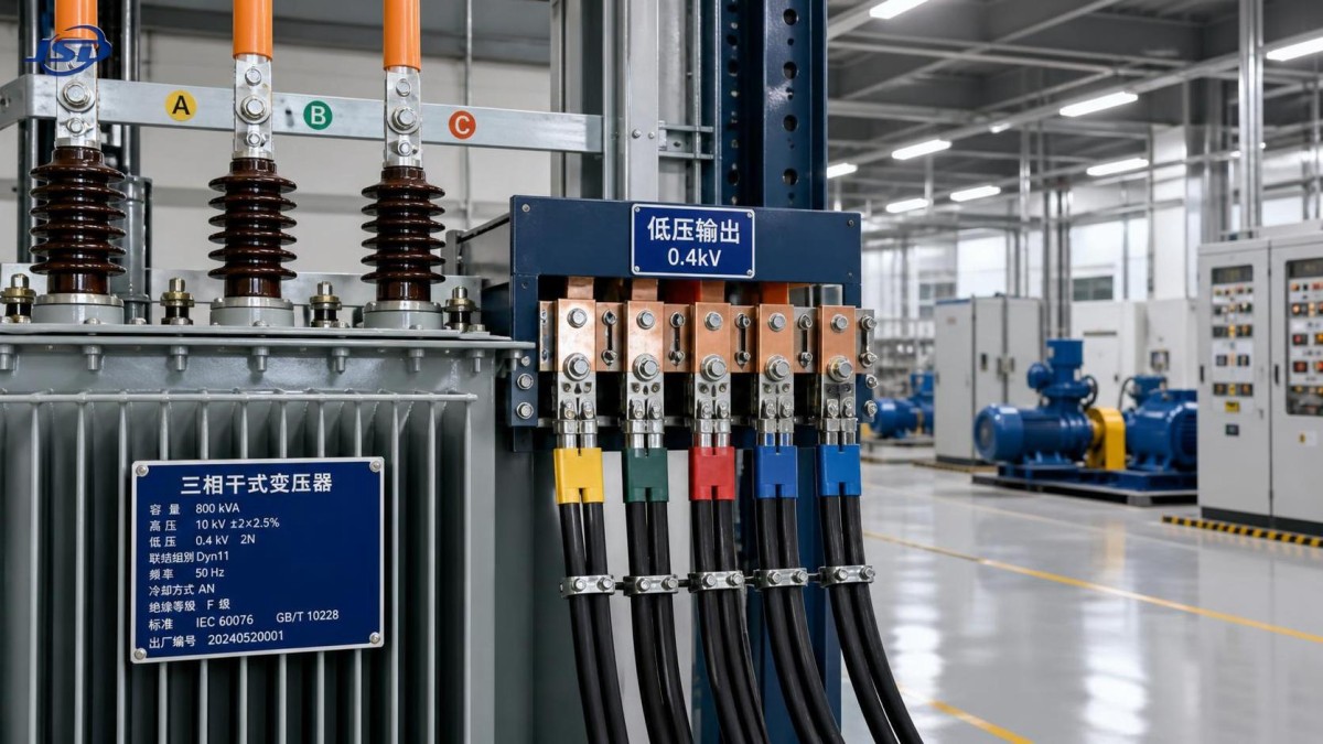
The first decision is not transformer kVA. It is identifying the available utility voltage, required secondary voltages, grounding arrangement, and the operating profile of every connected load.
Mixed-load facilities commonly combine motors, lighting, HVAC equipment, rectifiers, variable frequency drives, welding machines, control systems, and sensitive electronic equipment on one distribution network.
These loads do not behave alike. Motors create starting current, nonlinear loads generate harmonics, lighting may require stable voltage, and automation equipment can be highly sensitive to voltage disturbances.
Technical evaluators should document nominal supply voltage, voltage variation limits, phase sequence, frequency, fault level, grounding method, and expected utility reliability before selecting a 3 phase distribution transformer.
For example, a facility supplied at 11 kV may require a 400/230 V secondary system, while another location may use 13.8 kV primary and 480/277 V secondary distribution.
The chosen secondary voltage must support installed equipment without excessive local conversion. Unnecessary voltage conversion increases losses, introduces additional protection requirements, and complicates maintenance planning.
Where mixed loads include imported machinery, evaluators should verify whether equipment requires 400 V, 415 V, 440 V, 460 V, or 480 V operation at the specified frequency.
Voltage compatibility is especially important for motors and drives. A motor operating outside its intended voltage range may experience overheating, reduced torque, increased current, or shortened insulation life.
Control panels, programmable controllers, communication equipment, and instrumentation generally have narrower voltage tolerance than conventional resistive or induction motor loads.
A practical starting document is a load schedule showing each load category, connected kW, power factor, duty cycle, starting characteristics, harmonic behavior, criticality, and preferred operating voltage.
Use Demand, Diversity, and Load Growth Instead of Connected Load Alone
Connected load is useful, but it rarely represents the transformer’s continuous operating demand. Sizing from the total installed rating alone can result in unnecessary capital cost and poor efficiency.
Demand factor reflects how much of the connected load operates simultaneously. Diversity factor recognizes that individual peak demands generally occur at different times across a facility.
Evaluators should obtain operating data whenever possible. Historical interval demand, production schedules, seasonal loading, and future expansion plans provide a more defensible basis than assumptions alone.
For new projects, calculate several scenarios: normal production, peak production, startup conditions, emergency operation, and planned expansion. The transformer should meet the relevant continuous and short-duration requirements.
Motor-heavy sites require special attention because starting current can be several times full-load current. The key risk is usually voltage dip rather than transformer thermal capacity alone.
A transformer may have adequate kVA for normal operation but still produce unacceptable voltage sag when a large motor starts across the line.
Evaluate the largest motor start, the starting method, network impedance, transformer impedance, and simultaneous operating loads. Soft starters and variable frequency drives can materially change the result.
For intermittent welding, cranes, presses, and similar fluctuating loads, examine duty cycle and peak current. Thermal loading may remain acceptable while flicker or voltage fluctuation becomes problematic.
Future capacity should be considered explicitly. A modest growth allowance is usually appropriate, but excessive oversizing can reduce loading efficiency and create higher no-load energy losses.
Many projects target normal loading around 60 to 80 percent of transformer rating, although the appropriate figure depends on ambient conditions, harmonics, redundancy strategy, and growth certainty.
Select Transformer Voltage Ratio and Vector Group for the Distribution System
The voltage ratio must match the utility supply and downstream distribution architecture. This includes nominal primary voltage, secondary line voltage, neutral availability, and the facility’s equipment requirements.
For mixed commercial and industrial loads, a star-connected secondary is often valuable because it provides a neutral point for line-to-neutral lighting, controls, and single-phase auxiliary circuits.
A delta-wye configuration can also help isolate certain triplen harmonics and create a grounded neutral on the low-voltage side, depending on the overall grounding design.
However, vector group selection should never be treated as a catalog preference. It affects phase displacement, parallel operation, earthing behavior, fault current paths, and compatibility with upstream equipment.
When transformers operate in parallel, voltage ratio, impedance, vector group, tap position, and phase sequence must be compatible. A mismatch can cause circulating current or uneven load sharing.
Grounding requires coordinated review with protection engineers. The secondary neutral may be solidly grounded, resistance grounded, reactance grounded, or derived through another arrangement depending on regulations and fault objectives.
A grounded wye secondary often simplifies protection for common low-voltage distribution systems. Still, the fault level must remain within the interrupting ratings of downstream breakers and switchboards.
Technical evaluators should verify local grid standards and project specifications, including IEC, IEEE, ANSI, utility requirements, and regional voltage conventions before finalizing the design.
Tap changers deserve attention when the primary supply experiences routine voltage variation. Off-circuit taps may suit stable networks, while on-load tap changing may be justified for critical systems.
The objective is to keep load-side voltage within equipment tolerance under normal supply variation, expected transformer loading, and reasonably foreseeable distribution feeder voltage drop.
Account for Harmonics, Nonlinear Loads, and Energy Storage Interfaces
Modern mixed-load systems increasingly include variable frequency drives, UPS equipment, rectifiers, EV charging stations, photovoltaic inverters, and battery energy storage systems.
These devices can introduce harmonic currents that increase transformer losses, raise operating temperature, and affect voltage waveform quality. Standard transformer ratings may not fully represent this duty.
Harmonic current produces additional eddy-current losses in windings and structural parts. The effect grows with harmonic frequency, so a moderate distortion value can still create significant heating.
Request measured harmonic data for existing sites, or model expected distortion for new installations. Assess total harmonic current distortion, individual harmonic orders, and likely simultaneous nonlinear loading.
Where nonlinear load share is substantial, consider a transformer designed for harmonic duty, with suitable conductor sizing, thermal margins, and K-factor or equivalent design assessment.
Neutral conductors also require review. Triplen harmonics from single-phase nonlinear loads can add in the neutral of a wye-connected secondary rather than canceling each other.
Energy storage systems create another interface question. Their inverter determines how the battery system interacts electrically with the AC distribution network, not the battery’s nominal DC voltage alone.
For projects combining backup power, solar storage, and site distribution, the 51.2V Stackable LiFePO4 Energy Storage Battery can support modular storage arrangements through compatible inverter systems.
Its stackable capacity design, CAN and RS485 communication support, and intelligent battery management functions can assist projects requiring scalable residential or commercial energy storage configurations.
From the transformer perspective, assess inverter output voltage, maximum AC current, fault contribution, bidirectional power flow, anti-islanding behavior, and harmonic performance at each operating mode.
Check Impedance, Fault Duty, and Voltage Regulation Together
Transformer impedance is a central design parameter because it influences both available short-circuit current and voltage drop during changing load conditions.
Lower impedance generally increases secondary fault current, which can improve protective device operation but may exceed the withstand or interrupting ratings of downstream electrical equipment.
Higher impedance limits fault current, but it can worsen voltage regulation during motor starts or rapidly changing industrial loads. The correct value depends on system study results.
Do not select impedance only from a standard catalog range. Review the complete electrical network, including utility contribution, generator contribution, cable lengths, and parallel transformer arrangements.
A short-circuit study should calculate maximum and minimum fault levels at main switchboards, motor control centers, distribution boards, and major equipment connection points.
Maximum fault current confirms equipment withstand capability. Minimum fault current helps verify that protective devices can detect and clear faults within required operating times.
Voltage regulation should be assessed at full load and under critical load transitions. The transformer’s impedance, winding resistance, power factor, and feeder impedances all influence delivered voltage.
For sensitive mixed loads, evaluate the voltage at the equipment terminals, not only at the transformer secondary terminals. Long feeders can create substantial additional voltage drop.
Coordination with protection engineers is essential. Relay settings, breaker curves, fuse ratings, ground-fault protection, and selective coordination should reflect the selected transformer impedance and grounding method.
These studies are particularly important where critical process loads, healthcare equipment, data systems, or life-safety systems share distribution infrastructure with high-demand industrial equipment.
Evaluate Efficiency, Cooling, Environment, and Installation Constraints
Voltage selection and transformer rating should support efficient operation across the expected load profile. Transformer losses consist mainly of no-load core loss and load-dependent winding loss.
A lightly loaded transformer may have low winding losses but still consume continuous core-loss energy. An overloaded transformer has higher winding losses and elevated thermal stress.
Compare guaranteed loss values at realistic operating points rather than comparing purchase price alone. Energy cost over the transformer’s service life can materially exceed initial equipment cost.
Cooling method must suit the installation environment. Oil-immersed transformers offer robust performance for many outdoor and industrial installations, while dry-type units may suit indoor fire-sensitive locations.
Ambient temperature, altitude, ventilation, enclosure arrangement, contamination, humidity, and solar exposure can all require derating or specialized construction features.
In coastal, chemical, mining, or high-dust environments, corrosion protection and insulation system selection deserve early attention. Environmental conditions often determine long-term reliability more than nominal rating.
Noise may also matter in commercial buildings, urban infrastructure, hospitals, and residential-adjacent installations. Review guaranteed sound levels and consider placement, barriers, and enclosure design.
Physical constraints should be addressed before procurement. Confirm transport access, lifting points, foundation loads, clearances, cable routing, fire separation, and service access for future maintenance.
For installations with storage inverters, ensure adequate separation and ventilation between AC equipment, battery equipment, and transformer equipment according to applicable codes and manufacturer instructions.
A complete technical specification should state voltage ratio, kVA rating, impedance, vector group, taps, insulation class, cooling method, losses, standards, accessories, tests, and environmental requirements.
Use a Structured Technical Evaluation Before Issuing the Purchase Order
A defensible transformer selection process combines electrical studies with equipment data. It should not rely solely on a supplier’s recommended rating or a previous project’s standard configuration.
Begin with a verified load schedule and single-line diagram. Then confirm utility conditions, secondary voltage needs, maximum demand, growth assumptions, motor starting requirements, and harmonic sources.
Next, perform load flow, voltage drop, short-circuit, protection coordination, and harmonic assessments appropriate to the project’s complexity and operational risk.
Compare candidate transformer options using the same assumptions. Review kVA, voltage ratio, impedance, loss values, temperature rise, cooling, tap range, vector group, and physical dimensions.
Ask suppliers to provide routine test results, type-test evidence where required, drawings, guaranteed losses, temperature-rise information, insulation details, and applicable certification documentation.
Manufacturing quality should be part of the evaluation. Winding workmanship, core construction, insulation processing, oil treatment, test discipline, and quality controls affect long-term field performance.
For international projects, confirm that the equipment satisfies destination-country standards, utility interface requirements, shipping constraints, and local maintenance expectations before approving the design.
Jinshida Electric Power Technology Co., Ltd. supports transmission and distribution applications through engineering-focused manufacturing, quality management, and power equipment solutions for global projects.
Early technical communication helps align transformer configuration with grid conditions, industrial processes, renewable integration, infrastructure requirements, and the project’s reliability objectives.
The best 3 phase distribution transformer is therefore not simply the largest available unit. It is the unit whose voltage, capacity, impedance, protection compatibility, and losses match the real operating system.
Conclusion: Make Voltage Selection a System Decision
Selecting a 3 phase distribution transformer voltage for mixed loads should begin with the actual electrical system, not with a generic nameplate rating or an isolated equipment catalog.
Technical evaluators should prioritize supply compatibility, secondary voltage needs, load diversity, motor starting performance, nonlinear loading, fault duty, grounding, efficiency, and future capacity requirements.
When these factors are reviewed together, the selected transformer can provide stable voltage, manageable fault levels, improved equipment protection, lower lifecycle energy cost, and dependable long-term operation.
A disciplined study-led approach also reduces late-stage redesign, avoids unsuitable transformer configurations, and gives project stakeholders a clear technical basis for procurement and operational decisions.

Get a Quote
Regardless of whether you require general advice or specific support, we are happy to help you.
Send Us Your Inquiry Today

Jinshida Electric remains committed to contributing to global energy development through professional manufacturing and superior service.