





What ventilation does a transformer indoor installation require
For any transformer indoor installation, ventilation is a critical design factor that directly affects safety, efficiency, and equipment lifespan. Project managers and engineering leaders must ensure sufficient heat dissipation, airflow planning, and compliance with local electrical standards before commissioning. Understanding the ventilation requirements of a transformer indoor setup helps reduce operational risks, prevent overheating, and support reliable performance in industrial, grid, and infrastructure applications.
What Project Leaders Really Need to Know About Transformer Indoor Ventilation
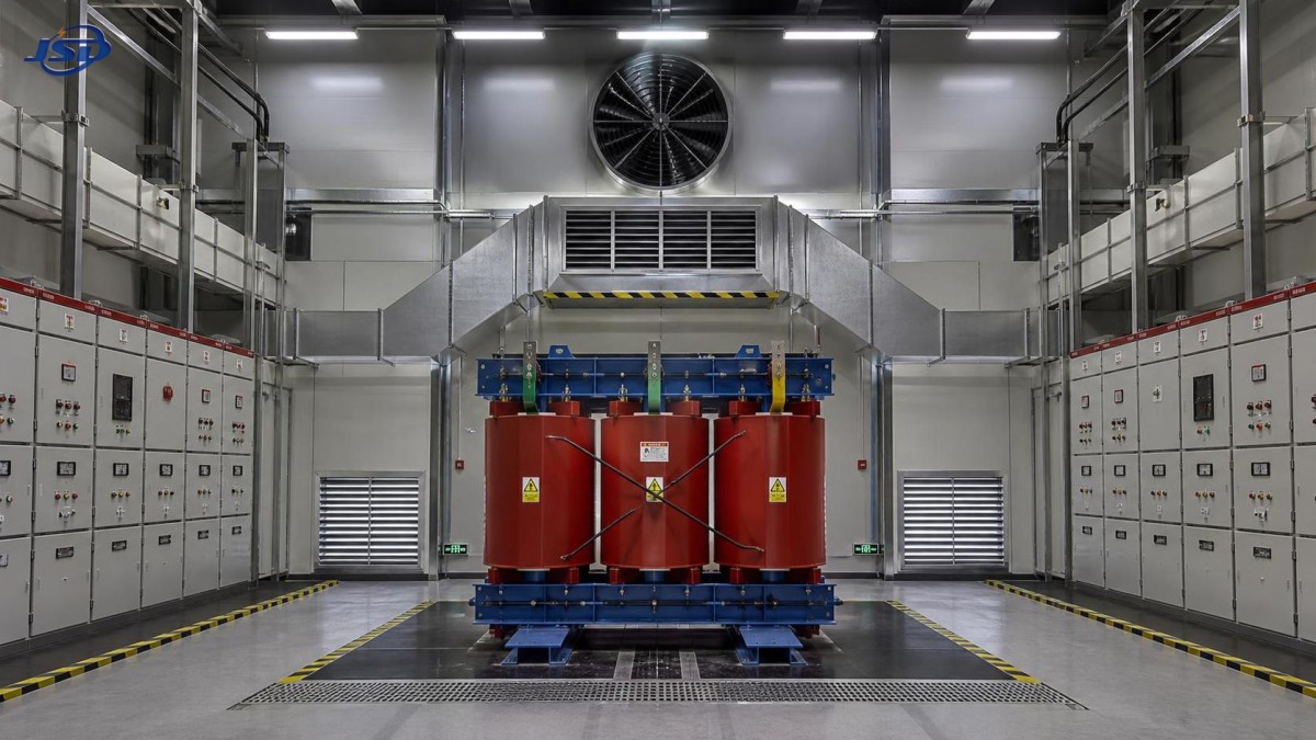
The core search intent behind “What ventilation does a transformer indoor installation require” is practical, not theoretical. Most readers want to know how much ventilation is needed, what risks poor airflow creates, and how to judge whether an indoor transformer room is adequately designed.
For project managers, the issue is rarely just airflow volume. It is about avoiding overheating, preventing premature insulation aging, reducing shutdown risk, and making sure the installation passes design review, inspection, and long-term operational expectations.
In simple terms, any transformer indoor installation requires ventilation that can continuously remove the heat generated during operation while keeping room temperature within the transformer manufacturer’s allowable limits and within local code requirements.
The exact requirement depends on transformer rating, load profile, transformer type, room size, ambient temperature, installation layout, and whether cooling relies on natural airflow, forced ventilation, or air conditioning support.
Why Ventilation Matters More Than Many Indoor Transformer Projects Assume
Transformers convert electrical energy efficiently, but they still generate significant heat. Core losses and winding losses become room heat, and in an enclosed space that heat can build quickly if there is no reliable path for removal.
When a transformer room retains heat, operating temperature rises not only inside the equipment but also around cables, switchgear, and protective accessories. This can shorten insulation life, increase maintenance frequency, and weaken the reliability margin of the whole electrical system.
For oil-immersed transformers, ventilation also helps control the room environment around radiators and cooling surfaces. For dry-type transformers, it is even more important because heat is released directly into the indoor space.
From a business perspective, inadequate ventilation often leads to hidden costs. These include unplanned shutdowns, derating, accelerated asset aging, corrective retrofit work, and delays when operators discover thermal issues during commissioning or early operation.
How to Determine the Ventilation Requirement for a Transformer Indoor Room
The first step is to estimate how much heat the transformer releases. In practice, this is usually based on the manufacturer’s total losses at the expected operating load, including no-load loss and load loss.
If a transformer has total losses of several kilowatts, the ventilation system must remove at least that same amount of heat continuously. The higher the room temperature and the tighter the room enclosure, the more demanding the airflow design becomes.
Project teams should review five inputs early: transformer loss data, maximum ambient temperature, room dimensions, allowable temperature rise, and planned operating duty. These values determine whether natural ventilation is enough or whether fans are required.
As a basic engineering principle, ventilation design should move cool air in at low level and discharge hot air out at high level. This follows the natural upward movement of heat and improves cooling efficiency around the transformer body.
Openings must also be sized realistically. Louvers, screens, filters, and acoustic treatments reduce effective airflow area, so nominal opening size should never be treated as actual free ventilation area.
Natural Ventilation vs Forced Ventilation: Which Is More Suitable?
Natural ventilation may be suitable for smaller transformer indoor applications where heat loss is moderate, ceiling height is adequate, airflow paths are short, and local ambient conditions are not extreme. It has the advantage of lower operating cost and less maintenance.
However, natural ventilation is often insufficient in compact substations, basements, retrofit buildings, high-load industrial rooms, or hot climates. In those cases, forced ventilation gives better control and more predictable thermal performance.
Forced ventilation systems usually include intake and exhaust fans, temperature sensors, control panels, and sometimes redundancy provisions. For mission-critical projects, this approach provides better assurance that room temperature remains within the target range during peak demand.
Decision-makers should avoid choosing natural ventilation only to reduce upfront cost. If the thermal margin is too narrow, later upgrades can be more disruptive and expensive than installing mechanical ventilation correctly from the beginning.
What Room Design Details Most Often Affect Ventilation Performance
Ventilation success is strongly influenced by room arrangement, not only by fan capacity. A well-sized fan cannot compensate for poor airflow routing, blocked intake paths, or hot air recirculation around the transformer.
One common problem is placing intake and exhaust openings too close together. This can allow air to short-cycle between openings instead of sweeping heat away from the transformer and across the room.
Another issue is inadequate clearance around the transformer. If walls, barriers, cable trays, or auxiliary equipment restrict airflow around radiators or coils, the effective cooling performance may fall below design expectations.
Room height also matters. Hot air collects near the ceiling, so high-level exhaust placement is essential. In low-ceiling rooms, heat pockets can form quickly and require stronger mechanical extraction.
Dust, humidity, corrosive atmosphere, and salt exposure should also be considered. Ventilation is not only about volume; it must support a suitable operating environment without introducing contaminants that create new reliability problems.
What Standards and Compliance Issues Should Project Managers Check?
There is no single worldwide ventilation number that fits every transformer indoor installation. Requirements vary by transformer design, manufacturer instructions, building codes, fire regulations, and electrical standards used in the project region.
That is why project leaders should always check manufacturer documentation first. The transformer supplier typically defines maximum ambient temperature, required installation clearances, cooling class, and any mandatory ventilation conditions.
Local electrical codes and fire safety requirements may further affect room ventilation design. These can include minimum air changes, fire separation, smoke control, pressure relief considerations, and restrictions on opening placement.
For larger facilities, the ventilation concept should also be coordinated with building HVAC, fire detection, and emergency power systems. A transformer room cannot be treated as an isolated box if the wider facility systems affect heat removal or safe operation.
How to Evaluate Ventilation Risk Before Construction or Procurement
For project managers, the most useful question is not “Does the room have vents?” but “Can this room maintain acceptable transformer operating temperature under worst-case conditions?” That is the decision point that prevents expensive surprises later.
A sound pre-construction review should include thermal load calculations, airflow path drawings, free-area verification for louvers, fan duty selection, control logic review, and a check of what happens during high ambient summer operation.
It is also wise to confirm what happens if a ventilation fan fails. In critical applications, alarm points, standby fans, or temporary derating procedures may be necessary to avoid forced outages.
Where projects involve integrated power solutions, teams increasingly look at the thermal behavior of the whole electrical environment rather than a single device. That mindset is equally important in adjacent systems such as containerized storage platforms like the 1MW/2MWh Liquid Cooling Container Energy Storage System, where heat management is also central to safe and stable operation.
Common Mistakes in Transformer Indoor Ventilation Planning
One frequent mistake is using generic ventilation assumptions without checking the transformer’s actual loss data. Different transformer ratings and designs can produce very different heat loads even when the rooms look similar.
Another is overlooking future load growth. A room that performs adequately at partial load may become thermally stressed once the facility reaches full production or network expansion increases transformer utilization.
Some projects also underestimate maintenance access. Ventilation equipment itself needs inspection and service, and blocked filters or failed fans can quietly reduce cooling capacity long before visible equipment alarms appear.
Noise control can create another conflict. Acoustic louvers and enclosures may help with environmental compliance, but they also increase airflow resistance. This tradeoff must be designed, not assumed away.
What a Good Ventilation Strategy Looks Like in Practice
A good strategy begins with accurate transformer loss values and room conditions, then selects a cooling approach with enough operating margin. It also defines airflow direction clearly and ensures the physical layout supports that intended path.
In many industrial and infrastructure projects, the best answer is a hybrid approach: passive airflow features where possible, combined with temperature-controlled exhaust or supply fans for dependable peak-condition performance.
Monitoring should not be treated as optional. Temperature sensors in the room and at critical equipment zones help operators verify whether the transformer indoor environment matches design assumptions after commissioning.
For owners managing modern electrical assets across substations, industrial plants, and energy systems, the same principle applies broadly: thermal management must be designed as part of equipment reliability, not added as a late corrective measure. This is one reason advanced packaged systems, including the 1MW/2MWh Liquid Cooling Container Energy Storage System, increasingly emphasize controlled cooling as a core design feature.
Conclusion: Ventilation Should Be Treated as a Reliability Decision
The right ventilation for a transformer indoor installation is the amount and type of airflow needed to remove transformer heat under real operating conditions while meeting manufacturer requirements and local compliance rules.
For project managers and engineering leaders, the practical takeaway is clear. Do not judge ventilation by room appearance or rule-of-thumb openings alone. Base the decision on transformer losses, airflow path quality, environmental conditions, equipment clearance, and failure risk.
When ventilation is designed correctly, the benefits are measurable: lower overheating risk, longer equipment life, smoother commissioning, and stronger operational continuity. In transformer projects, ventilation is not a secondary room detail. It is part of the asset protection strategy.

Get a Quote
Regardless of whether you require general advice or specific support, we are happy to help you.
Send Us Your Inquiry Today

Jinshida Electric remains committed to contributing to global energy development through professional manufacturing and superior service.