





Why does an indoor transformer overheat in a closed room
Why an Indoor Transformer Overheats in a Closed Room
When an indoor transformer runs hot in a closed room, the problem is rarely mysterious. In most field situations, heat is not being removed as fast as it is being generated. That sounds simple, but the reasons behind it are not always simple at all. A room may look acceptable on paper and still trap heat in actual operation. A transformer may be loaded within nameplate limits and still overheat because the ambient temperature is already too high. Sometimes the unit is healthy, and the room is the real fault. Sometimes it is the opposite.
For maintenance teams, the practical question is not just “why is it hot,” but “what is creating heat faster than normal, and what is preventing heat from leaving the transformer room?” That distinction matters, because replacing sensors or cleaning terminals will not solve a ventilation problem, and adding fans will not fix an overloaded winding.
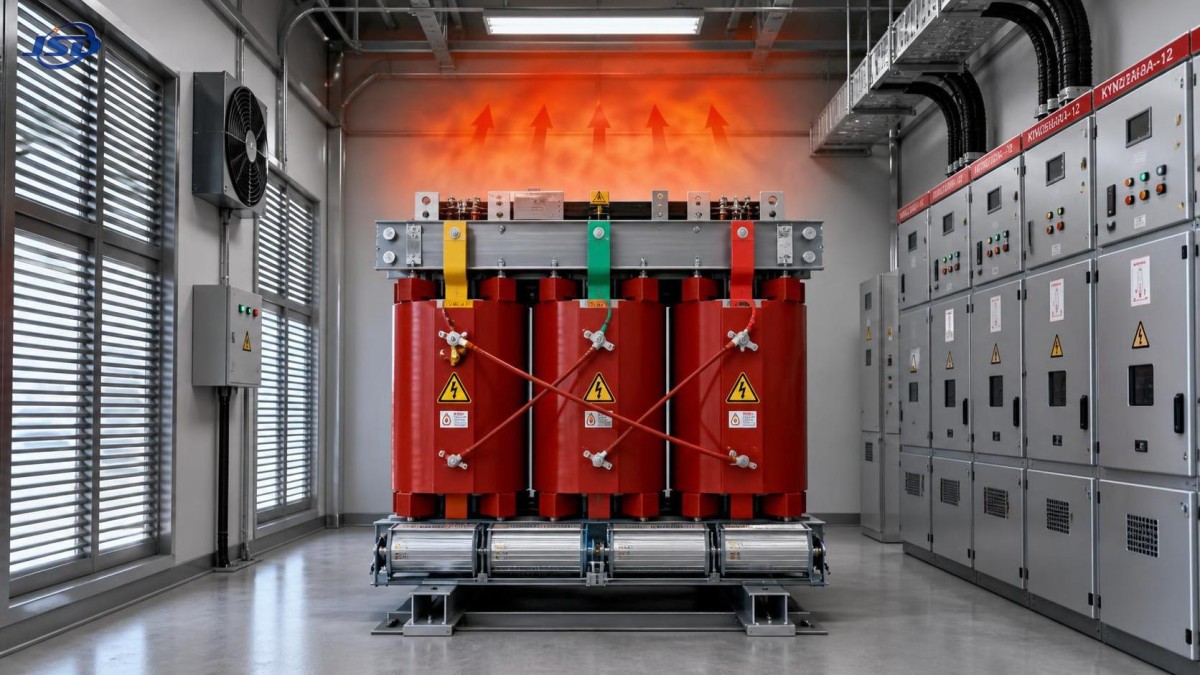
An indoor transformer depends heavily on surrounding conditions. In a closed room, natural convection is weak, hot air accumulates near the top of the enclosure, and the transformer begins to operate in its own exhaust heat. Once that happens, winding temperature rises faster, insulation ages faster, and even routine load swings can push the unit into alarm or trip conditions.
The first thing to check: is the room itself the problem?
In after-sales work, one of the most common misunderstandings is assuming that a closed room is acceptable as long as the transformer has enough physical space around it. Space alone is not ventilation. If there is no effective air intake, no hot-air discharge path, or no mechanical air exchange, the room becomes a heat box. This is especially common in retrofit projects where a transformer is moved into an existing electrical room that was never designed for continuous heat rejection.
A quick field clue is the difference between room temperature and transformer surface temperature. If the room feels unusually hot before you even approach the unit, the transformer may be overheating because the ambient condition is already outside a comfortable operating range. Another clue is whether the room cools down slowly after load decreases. A room that stays hot long after peak demand usually has poor airflow rather than a brief loading issue.
Doors kept closed for dust control, security, or noise reduction often make things worse. So do blocked louvers, cable trenches that restrict air movement, and false ceilings that trap rising heat. In some sites, maintenance staff find that exhaust fans exist but are undersized, disconnected, or running opposite to the intended airflow path.
Load may be “normal” on paper and still too high in practice
Transformers generate losses under all operating conditions, and those losses increase with load. Copper loss is particularly sensitive to current, so a unit running near its upper loading range for long periods will heat up much faster than one carrying a moderate and stable load. In a closed room, that extra heat has nowhere to go.
This is where field judgment matters. A maintenance record may show that the transformer is not overloaded by nameplate rating, but that does not automatically mean the temperature rise is acceptable. Nameplate assumptions are tied to installation conditions, cooling mode, and ambient environment. If the actual room temperature is high, if nearby equipment adds heat, or if airflow is poor, the same load can become unsafe.
Look beyond average load. Short but repeated demand spikes, harmonic-rich loads from drives or rectifiers, and uneven phase loading can all increase internal heating. These conditions are easy to miss if the site only checks current periodically instead of using trend data.
Poor connections and local hot spots can imitate a ventilation problem
Not every overheating event starts in the winding. In real maintenance work, loose terminals, oxidized joints, undersized cable lugs, and contaminated contact surfaces often create localized resistance heating. The room may be warm, but one connection point is much hotter than the rest. That is a different failure mode and usually shows up in thermal inspection as a concentrated hot spot rather than a uniform temperature rise across the whole transformer body.
This matters because local heating can gradually spread. A hot termination raises the temperature of adjacent conductors and enclosure air, which then makes the whole transformer room seem like the issue. If you only improve ventilation, you may reduce symptoms without removing the actual fault.
The same logic applies to tap changer contacts, busbar joints, and cable terminations. A full check should include torque verification where permitted by maintenance procedures, thermal imaging under load, and visual inspection for discoloration, smell, or insulation hardening.
Dust, clogged cooling paths, and installation layout are often underestimated
Indoor installations are sometimes assumed to be clean environments, but many are not. In industrial plants, closed rooms can still accumulate dust, oil mist, fibers, or corrosive deposits. On dry-type units, blocked ventilation ducts and dirty cooling surfaces reduce heat dissipation directly. On other designs, nearby walls or switchgear may restrict airflow around the transformer body and force hot air to recirculate.
Clearance problems are especially common after later modifications. A room that originally had acceptable spacing may gradually fill with cables, spare parts, panels, or temporary barriers. Each small change seems harmless, but together they disrupt the thermal path. Maintenance staff often focus on electrical integrity and overlook how much installation geometry affects cooling.
At Jinshida Electric Power Technology Co., Ltd., projects in grid, industrial, new energy, and infrastructure environments often show the same lesson: reliable transformer operation depends not only on product quality, but also on whether the actual site conditions match the intended application. A professional technical team can design a robust unit, yet field performance still depends on heat management, room layout, and operating discipline.
Do not ignore upstream and downstream system effects
Sometimes the transformer is running hot because the broader power system is forcing it into a difficult operating pattern. Frequent starts of large motors, poor power quality, harmonics from power electronics, or repeated charge-discharge cycling from nearby energy assets can all change the thermal profile. In facilities that combine transformers with flexible backup or mobile power systems, load transfer events should be reviewed carefully.
For example, if a site uses temporary support equipment such as a 50kW/100kWh Portable Trailer Energy Storage System during maintenance windows, commissioning, or emergency supply transitions, the transformer loading pattern before and after switching may not resemble normal steady-state operation. That does not mean the storage unit is a problem; it means temperature behavior should be judged in the full operating sequence, not in isolation.
A practical troubleshooting sequence that works on site
When you arrive at a hot indoor transformer room, resist the urge to jump straight to one explanation. Work from the environment inward.
- Check ambient room temperature and whether heat is trapped near the ceiling or around the transformer.
- Confirm that intake and exhaust paths are open, fans are operating, and airflow direction makes sense.
- Compare actual load current by phase with the transformer’s expected operating condition.
- Look for recent changes: new equipment, blocked vents, altered room access, or seasonal temperature shifts.
- Use thermal imaging to identify whether heating is general or concentrated at specific terminals or joints.
- Inspect for dust buildup, restricted cooling passages, and inadequate spacing from walls or adjacent equipment.
- Review alarms, temperature sensors, and protection settings, but do not assume the instrument is wrong unless other checks support that conclusion.
That order helps separate room-related overheating from electrical faults. It also prevents a very common maintenance mistake: replacing parts before understanding the thermal environment.
When the sensor says “overheat,” verify what is really overheating
Temperature alarms are valuable, but they do not tell the whole story by themselves. A sensor may be reading winding temperature, core temperature, room temperature, or a point near the air outlet depending on the design. If the alarm threshold has been adjusted incorrectly, or if the sensor location is not representative, the maintenance team can waste hours chasing the wrong issue.
It is good practice to compare sensor readings with an independent measurement method where possible. If the indicated value is high but the surface temperature and room condition do not match, further checking is justified. On the other hand, if the room is clearly overheated and every external sign points to poor cooling, debating the sensor is usually a distraction.
What usually fixes the problem
In many closed-room indoor transformer cases, the corrective action is not exotic. Improve ventilation. Remove airflow obstructions. Restore design clearances. Clean cooling passages. Tighten and refurbish hot connections where inspection confirms local resistance heating. Rebalance or reduce load if operation has drifted away from the original assumptions. If harmonics or repeated peaks are present, those need to be addressed at system level rather than treated as a transformer-only issue.
Where equipment selection or room design is being reconsidered, it helps to work with manufacturers that understand both product performance and site application. Jinshida Electric’s focus on R&D, manufacturing discipline, and practical power distribution use is relevant here for one reason: transformer reliability is rarely just a factory question. It is an installation question, a thermal question, and a maintenance question at the same time.
If an indoor transformer overheats in a closed room, assume there is a real cause until proven otherwise. Heat is cumulative, insulation aging is not reversible, and repeated temperature excursions tend to come back as larger failures later. In the field, the best results usually come from calm observation, load verification, and a hard look at whether the room is actually letting the transformer breathe.

Get a Quote
Regardless of whether you require general advice or specific support, we are happy to help you.
Send Us Your Inquiry Today

Jinshida Electric remains committed to contributing to global energy development through professional manufacturing and superior service.