





What to verify before installing a three phase open frame diesel generator
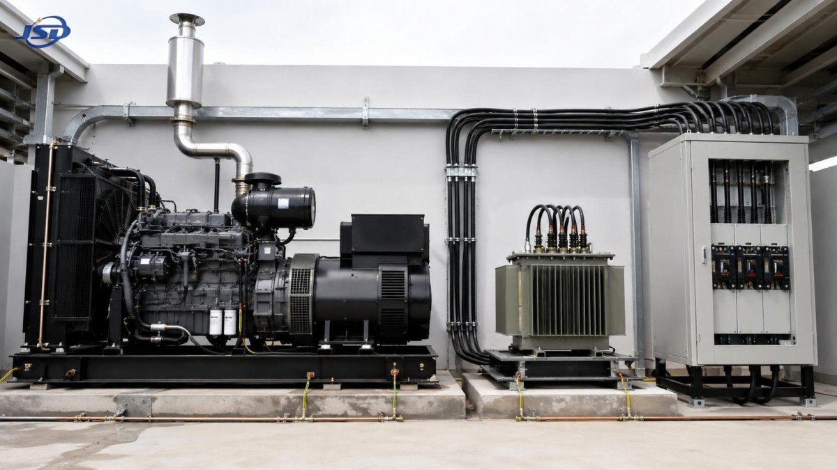
A three phase open frame diesel generator should not be treated as a stand-alone engine with an alternator attached. Once it is connected to a distribution board, transformer, automatic transfer equipment, motors, or sensitive electronic loads, it becomes part of a power system. Most installation failures come from a mismatch between that system and the generator’s actual electrical, mechanical, and environmental limits.
Before approving installation, verify the load profile, voltage and frequency arrangement, neutral and earthing design, cable and protection coordination, ventilation path, fuel arrangement, foundation, and operating sequence. These checks should be completed before equipment is positioned or terminated, because correcting them after commissioning is usually more disruptive and expensive.
Start with the load profile, not only the generator nameplate
The first question is not “What is the total connected load?” It is “What load will the generator see at each stage of operation?” A connected-load list often overstates continuous demand while failing to show the momentary starting current that can cause the larger problem.
Separate loads into groups: continuous loads, intermittent loads, motor loads, heating loads, rectifier or UPS loads, and loads that must start after a grid outage. Record which equipment runs together, which equipment starts first, and whether starting is direct-on-line, star-delta, soft-started, or controlled by a variable-frequency drive.
Motors deserve particular attention. A generator that supports the running kW of a pump, compressor, crusher, or fan may still experience an unacceptable voltage dip when that motor starts. The result can be failed motor acceleration, contactor dropout, controller resets, or instability in other loads sharing the bus. Sequenced starting, reduced-voltage starting, or a larger generating set may each be valid solutions, depending on the site duty.
Also identify nonlinear loads, such as rectifiers, welding equipment, variable-speed drives, and some battery charging systems. Their current waveform can affect alternator heating and voltage regulation differently from a simple resistive load. The review should therefore use supplier data and the expected operating arrangement rather than applying one generic loading rule to every installation.
Confirm the electrical interface from generator terminals to the load bus
A three phase open frame diesel generator must match the receiving system in voltage, frequency, phase configuration, and neutral arrangement. A nominal voltage match alone is insufficient. Verify whether the installation uses a three-wire or four-wire system, whether a neutral conductor is required by downstream loads, and where the neutral-to-earth bond is intended to exist.
The planned operating frequency must also match the equipment being supplied. Frequency affects motor speed, transformer behavior, and the operating characteristics of some control equipment. A set configured for one frequency should not be assumed suitable for a system designed around another without reviewing the engine speed, alternator rating, and connected loads.
Check phase rotation before final connection, especially where pumps, fans, conveyors, or other rotating machines are involved. Incorrect phase sequence can reverse motor direction. That may create an immediate mechanical hazard or cause a process failure that is not obvious until equipment is placed in service.
Transformer-fed installations need an additional review. Confirm the transformer ratio, vector group implications, low-voltage neutral arrangement, impedance, and expected inrush behavior. A generator may supply an existing transformer successfully in steady operation but struggle during transformer energization if switching is not controlled. The same review applies to capacitor banks: they should not be assumed to be harmless simply because their steady-state current is low.
Make grounding and neutral bonding an intentional design decision
Grounding is often discussed as a single installation item, but generator systems require two related decisions: how exposed conductive parts are earthed, and how the system neutral is referenced to earth. Those decisions affect fault current, protective-device operation, and safety during both utility and generator operation.
A common error is to add a neutral-earth bond at the generator without considering the transfer switch and the utility supply arrangement. If the generator operates through a transfer device that does not switch the neutral, an additional bond can create parallel neutral return paths and circulating current. If the generator is intended to operate as a separately derived source, the bonding and grounding arrangement has different implications. The correct configuration depends on the full distribution architecture, not on a universal wiring diagram.
Verify the continuity and capacity of protective earth conductors, the earthing electrode arrangement where applicable, bonding of the generator frame and fuel-related metallic components, and the earth-fault protection method. Earth-fault protection that works reliably on the normal utility source may not respond in the same way when the source changes to a generator with lower available fault current.
Protection coordination must work on generator power, not only on utility power
The utility network can normally provide high fault current. A diesel generator has a more limited and time-dependent fault-current contribution. This changes how breakers and fuses behave during a fault. A protective device selected only for utility conditions may not clear a downstream fault as expected when the generator is supplying the bus.
Review the generator breaker, feeder protective devices, overload settings, short-circuit settings, earth-fault functions, and discrimination with downstream devices. The objective is practical: a fault on one feeder should be cleared by the closest appropriate protective device, while the generator and unaffected circuits remain protected.
Do not overlook cable sizing. Conductors must be suitable for expected current, installation method, ambient temperature, grouping, voltage drop, and fault duty. Long temporary cable runs are particularly prone to voltage drop, which can make motor starting worse and reduce the voltage available at remote equipment even when the generator terminals appear normal.
Where an automatic transfer switch is used, verify its current rating, pole configuration, interlocking, switching mode, and control logic. It must prevent unintended parallel operation unless the system has specifically been designed for synchronizing and closed-transition transfer. Backfeeding a utility network or another source is a major safety risk and can damage equipment.
Open-frame construction changes the site requirements
An open-frame set is practical where access, inspection, and portability matter, but it depends heavily on the installation environment. Unlike an enclosed package, it does not provide the same built-in weather, sound, access-control, or airflow management.
Choose a location with a stable, level support surface that can carry the equipment and resist vibration movement. The base should keep the unit clear of standing water, loose debris, and vehicle impact routes. Flexible connections or appropriate vibration isolation may be needed where vibration could be transmitted into structures, fuel piping, or rigid cable systems.
Airflow must be assessed as a path, not merely as open space around the unit. The engine needs a reliable supply of clean combustion and cooling air, while hot discharge air and exhaust must not recirculate into the intake area. Recirculation is a frequent cause of high operating temperature under load. It can occur in plant rooms, under canopies, beside walls, or between closely placed equipment even when the site initially looks open.
Outdoor installation requires protection against rain, direct water entry, dust accumulation, corrosive atmospheres, and unauthorized contact with live or hot parts. A canopy or shelter must not restrict cooling airflow. Exhaust routing should keep fumes away from doors, air intakes, work areas, and nearby equipment. Exhaust components become hot in normal service, so separation from combustible materials and accessible guarding matter as much as routing.
Review fuel storage, run time, and maintainability together
Fuel planning is more than selecting a tank volume. Establish the required operating duration, expected load range, refueling method, fuel transfer route, and the consequences of a missed delivery. A set used for short emergency duty may have a different fuel strategy from one used as prime power at a remote site.
Fuel must remain clean and protected from water contamination. Storage location should allow safe access for delivery and maintenance while keeping fuel away from ignition sources and vulnerable traffic areas. Long fuel lines, elevated tanks, and external transfer pumps introduce operational dependencies that should be included in the commissioning scope.
Leave access for routine checks: oil level, coolant level, filters, belts, battery terminals, control panel, breaker operation, and drainage points. A generator can be electrically well designed but operationally weak if basic maintenance requires removing barriers, working in unsafe positions, or interrupting adjacent equipment.
Temporary distribution needs a complete source-to-load plan
Construction work, emergency restoration, mining activity, and temporary infrastructure projects often combine an open-frame generator with portable distribution equipment. In these cases, the generator is only one part of the solution. The transformer, high- and low-voltage switchgear, protection devices, cabling, and operating controls must be assessed as one connected package.
For projects that need a transportable distribution point rather than only low-voltage generator output, a Mobile Temporary Compact Substation can be relevant. Trailer-mounted or skid-mounted arrangements can integrate transformation, switching, protection, and control for temporary three-phase distribution. The useful question is whether the project needs a rapidly deployed medium-voltage-to-low-voltage interface, not simply whether mobile equipment is available.
Its stated configurations cover 500 kVA to 1250 kVA capacities, high-voltage options from 10 kV to 35 kV, and 0.4 kV low-voltage output. That does not eliminate the need for generator checks. The generator voltage, frequency, fault behavior, transformer energization sequence, protection settings, and earthing arrangement still need to be coordinated with the temporary substation and final loads.
Commissioning should test the operating sequence, not just prove that the engine starts
Before placing the system into service, inspect all mechanical fixings, cable terminations, protective conductor connections, fuel connections, exhaust routing, fluid levels, battery condition, and control wiring. Verify insulation condition where appropriate and confirm that labels match the final circuit arrangement.
Functional testing should include start and stop commands, emergency stop behavior, alarms, breaker operation, transfer logic, phase sequence, voltage and frequency stability, and protective trips. Apply load progressively and observe the response of the generator and connected equipment. Where large motors or transformer energization are part of normal operation, test the actual intended sequence rather than relying solely on an unloaded run.
Document the final settings and operating positions. The useful record includes single-line diagrams, protection settings, cable schedules, earthing details, transfer-switch logic, operating instructions, and maintenance access requirements. This documentation becomes particularly important when a temporary installation changes hands or is expanded later.
Common approval mistakes
- Selecting by kVA alone: This ignores motor starting, load steps, power factor, and nonlinear current.
- Assuming an open frame is suitable for any outdoor area: Weather exposure, exhaust discharge, dust, and access control still require site-specific measures.
- Copying the utility protection settings: Generator fault behavior can require a different coordination approach.
- Treating the neutral as an installation detail: Neutral switching and bonding affect both safety and nuisance faults.
- Testing only at no load: The problems that matter often appear during load acceptance, motor starting, or source transfer.
- Leaving no maintenance clearance: Restricted access encourages missed inspections and delayed fault response.
A reliable installation is usually decided before the generator arrives on site. When the load sequence, electrical interface, protective devices, earthing arrangement, environment, and commissioning tests are defined together, the generator can provide stable support instead of becoming the weakest element in the distribution system.

Get a Quote
Regardless of whether you require general advice or specific support, we are happy to help you.
Send Us Your Inquiry Today

Jinshida Electric remains committed to contributing to global energy development through professional manufacturing and superior service.