





What routine tests keep a neutral grounding transformer reliable?
A reliable neutral grounding transformer is maintained by testing the electrical path that carries earth-fault current, the insulation system that keeps the transformer isolated during normal service, and the connections that must withstand short-duration fault duty. A clean enclosure and normal-looking bushings are useful observations, but they do not confirm that the neutral point, grounding resistor connection, windings, and protection circuits will perform correctly during a fault.
Routine work should begin with the latest approved nameplate data, wiring diagram, previous test records, and protection settings. Test values become meaningful when compared with the unit's own baseline, measured under similar temperature and isolation conditions. A single reading without its test method, temperature, tap position, and terminal configuration can lead to an incorrect service decision.
Start with the grounding circuit, not only the transformer
A neutral grounding transformer often creates an artificial neutral for a delta or otherwise ungrounded system, commonly through a zigzag winding arrangement. Its grounding conductor may connect directly to earth or through a neutral grounding resistor. The complete fault-current path therefore includes more than the transformer tank: neutral bushing, resistor or reactor, links, cable terminations, earth conductor, grid connection, current transformer, and protective relay input all require attention.
Before electrical tests, isolate, lock out, discharge, and prove the equipment de-energized according to the approved site procedure. Remove temporary grounds only when the test arrangement requires it, then restore all operating grounds before release. A missed neutral-to-resistor link after testing can leave the system without its intended fault-current limitation even though the transformer itself has satisfactory insulation values.
Continuity and connection integrity
Measure continuity through the neutral conductor and, where accessible, through the resistor or reactor circuit. The result should be stable and consistent with the known conductor length and component design. A low resistance result is not automatically proof of a sound circuit. Loose bolted joints, corrosion beneath lugs, damaged braid, or a partially fractured conductor can remain hidden under a low-current continuity test. Inspect contact surfaces, hardware tightness, discoloration, cable support, and strain relief at the same time.
For a resistor-grounded arrangement, confirm that the resistor value is appropriate to the documented design and that the resistor grid has no broken elements, bypassed sections, or signs of overheating. Test lead resistance must be accounted for when the expected resistance is low. A four-wire measurement is preferable where lead and contact resistance would otherwise materially affect the reading. Do not infer resistor health from its external appearance; an element can be electrically open while retaining its original shape.
Check the earth path separately. Verify bonding between the tank, grounding transformer neutral system, resistor enclosure, surge protection equipment, and the designated earthing point. The acceptable earth resistance depends on the site grounding design and cannot be judged by applying a generic value. More useful questions are whether the measured result has changed materially from its established condition and whether all intended metallic parts are bonded without parallel paths masking a failed connection.
Insulation resistance needs context
Insulation-resistance testing is a routine screening tool for winding-to-earth and, where the winding configuration permits, between isolated winding sections. Test each intended circuit with unrelated terminals grounded or guarded as required by the test procedure. Record test voltage, duration, ambient temperature, winding temperature where available, humidity, surface condition, and whether cable connections or arresters were removed. These details often explain a reading that appears unusual.
A reduced value can result from moisture absorption, contamination on bushing surfaces, deteriorated lead insulation, internal insulation aging, or an external circuit that was not fully isolated. A high value should also be interpreted carefully. It does not prove that winding turns are intact, that the neutral connection is continuous, or that a resistor circuit will carry its specified fault duty.
Where the equipment history and procedure support it, compare the time-resistance behavior during the test. A steadily rising reading is generally more reassuring than a flat or falling trend, but a polarization index should not be treated as a stand-alone pass or fail criterion. Small, dry, or temperature-sensitive windings may not display the same time response as larger power-transformer windings. A significant departure from the unit's previous pattern warrants investigation, particularly after flooding, extended storage, enclosure condensation, or a fault event.
Clean and dry contaminated external insulation before condemning the internal winding system. Retest after the surface condition is corrected. If the value remains depressed, isolate external cables, surge arresters, voltage transformers, and monitoring devices one by one where the design allows. This controlled separation prevents unnecessary removal of a sound grounding transformer because an attached component is leaking to earth.
Winding tests reveal faults that insulation resistance misses
Winding resistance measurement is one of the most useful routine tests for identifying loose internal joints, damaged connections, tap-selector problems, and unequal current paths. Use a stable DC test current and wait for the reading to settle; inductive windings need time to charge. Record the winding temperature and normalize comparisons where the maintenance procedure requires temperature correction. Compare corresponding phase paths and compare with prior records using the same terminal arrangement.
For a zigzag grounding transformer, the connection pattern makes interpretation more demanding than for a simple two-winding transformer. The measured path may contain portions of windings on different core limbs, so values should be assessed against the approved factory data or a verified historical baseline rather than assumed equal merely because the installation is three-phase. A sudden imbalance deserves attention, while a small consistent difference that has existed since commissioning may reflect the winding design and lead arrangement.
Transformer turns ratio and excitation-current tests add a different view of the magnetic circuit and winding connections. Ratio testing should use the applicable vector relationship and test points stated for that transformer design. A ratio issue may indicate an incorrect external connection, wrong tap position, a winding fault, or a test setup that does not respect the zigzag configuration. Confirm the diagram before repeating measurements.
Excitation-current readings are sensitive to residual magnetism, test voltage, core construction, and the phase being energized. A single phase with a markedly different response can indicate a core or winding concern, but residual flux can produce a similar pattern. Demagnetization and a repeat test under identical conditions are sensible before escalating the result. Do not use excitation current as a substitute for checking the neutral grounding circuit; it evaluates a different failure mode.
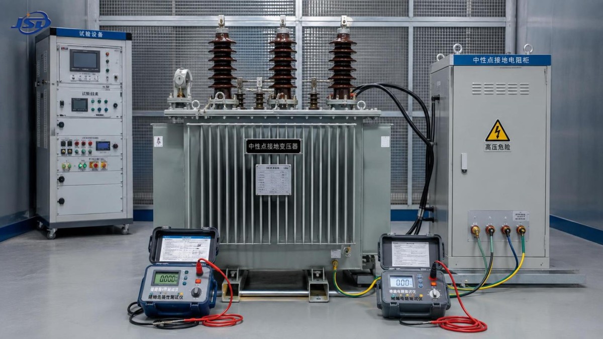
Verify fault-current control and protection interfaces
The grounding transformer does not operate in isolation. Its purpose is defined by the earth-fault current the system is intended to produce and the protective devices expected to detect it. Routine verification should therefore include the neutral current transformer polarity, ratio identification, secondary wiring continuity, terminal tightness, and relay test connection condition. An intact transformer paired with a reversed current-transformer polarity or an open relay circuit can produce misleading protection behavior.
Secondary injection is useful for confirming the relay input path, indications, alarms, trips, and any interlocks associated with earth-fault protection. This test does not prove that the grounding transformer can deliver the required primary fault current, but it exposes wiring and logic defects without imposing a system fault. Primary injection, where permitted by the site method and equipment rating, gives a more complete functional check of the current path. It needs careful planning because test current can heat the resistor, energize downstream circuits, or create unexpected indications.
Do not change a grounding resistor value or relay pickup simply because a recent earth-fault event appears too low or too high. First establish the fault location, system configuration, source contribution, current-transformer scaling, relay record quality, and whether the system neutral arrangement changed. A lower-than-expected recorded current may stem from a measurement chain issue, while an actual elevated current could involve an unintended parallel earth return rather than a failed resistor alone.
Thermal evidence should be read as a pattern
Infrared inspection during normal load or after a controlled test can locate hot terminals, resistor connections, cable lugs, and enclosure joints. Compare similar accessible connections under comparable current. An absolute temperature is less informative when ambient temperature, emissivity, wind, enclosure ventilation, and load are unknown. A localized hot spot at one neutral link is more significant than a uniformly warm resistor bank carrying current within its operating duty.
Thermal imaging requires sound technique. Painted metal, oxidized copper, shiny hardware, and viewing angle can distort apparent temperature. Confirm suspect findings with a contact method where safe and practical, then inspect torque, contact pressure, conductor strand condition, and oxidation. Repeated heating can relax bolted joints, while a loose joint itself creates resistance and further heating; that cycle can become evident well before insulation tests change.
For oil-filled units, inspect oil level, leaks, breather condition, pressure indications where fitted, and signs of moisture entry. Oil sampling or dissolved-gas analysis is justified when there is a fault history, abnormal heating, unexplained insulation deterioration, or a trend that suggests internal activity. It should not be used as a routine substitute for targeted electrical tests on a small or lightly loaded grounding transformer. Sample handling and laboratory comparison must be consistent, since poor sampling can obscure a meaningful trend.
External condition still matters when it is tied to a test decision
Inspect bushings for tracking, cracks, contamination, and evidence of discharge. Look closely at neutral terminals because they may be exposed to vibration, salt-laden air, rain ingress, or repeated thermal cycling. Check that cabinet gaskets, drainage paths, heater circuits, and ventilation screens remain effective. Water inside a resistor enclosure can lower insulation, corrode terminals, and alter the resistor's heat dissipation during an earth fault.
Outdoor installations deserve added attention after severe weather, transport, construction work, or changes to cable routing. A shifted cable support may pull on a bushing terminal; a new parallel metallic path can alter current distribution; a damaged enclosure heater can lead to condensation without any obvious external leak. These conditions are not interchangeable, so the follow-up test should match the observation rather than repeating every electrical test without a fault hypothesis.
Grounding transformers associated with renewable-energy collector systems can see frequent switching, fluctuating voltage, remote locations, and extended exposure to weather. Where an installation includes equipment such as a Transformer for Wind Power Generation, confirm the actual neutral arrangement at the point being tested. A three-phase step-up transformer with a Dyn11 or Yyn0 connection may have a neutral available on one side, while another section of the collection network may rely on a separate grounding transformer. Testing the wrong neutral point can create an apparently valid result that does not represent the protected system section.
Use trends and event records to decide the next action
Routine testing is most effective when results are recorded in a form that permits comparison. Keep terminal designations, tap position, temperature, test instrument, test voltage, isolated accessories, and observed conditions with each result. “Insulation good” or “resistance normal” is too vague to support later diagnosis. A consistent history also distinguishes gradual insulation aging from a sudden change after a fault, repair, or environmental event.
- Stable electrical readings with repeated local heating point first toward a connection, contact pressure, or resistor enclosure issue rather than an internal winding defect.
- Lower insulation resistance after humid weather, followed by recovery after drying and cleaning, suggests surface contamination or moisture ingress. The source of moisture still needs correction before the next wet period.
- Changed winding resistance with normal external terminals calls for closer review of internal leads, tap connections, and prior fault duty. Repeating the measurement after full stabilization is appropriate before opening equipment.
- Normal transformer tests but failed relay functional testing confines the defect to the measurement, control, or trip circuit until proven otherwise; it should not be cleared by a satisfactory megohmmeter result.
After any earth fault, examine protection records before resetting the equipment to routine status. Compare the measured or recorded fault current and duration with the intended grounding arrangement, inspect the resistor for thermal damage, repeat connection checks, and look for mechanical displacement at cable terminations. A transformer can survive a fault electrically while associated terminals or resistor elements have been weakened by the heat cycle.
The practical objective is a verified chain: sound windings and insulation, a continuous neutral path, the intended resistance or reactance to earth, and protection that measures and clears faults as designed. When those checks are performed with repeatable conditions and retained baselines, routine testing becomes a focused reliability tool rather than a collection of isolated readings.

Get a Quote
Regardless of whether you require general advice or specific support, we are happy to help you.
Send Us Your Inquiry Today

Jinshida Electric remains committed to contributing to global energy development through professional manufacturing and superior service.