





When is a zig zag grounding transformer better than a wye unit?
A zig zag grounding transformer is often the stronger choice when a three-phase system needs an artificial neutral, controlled ground-fault current, and little or no influence on normal load voltage. That combination is particularly valuable in ungrounded or delta-connected medium-voltage networks, where a single line-to-ground fault should be detected and cleared predictably rather than becoming a prolonged operational uncertainty.
For a technical evaluator, the question is rarely “Which transformer is better in general?” The real question is whether the system needs only a neutral point, a dedicated ground-fault return path, phase-to-neutral loading capability, or some combination of these functions. A wye-connected grounding unit and a zig-zag design can both support grounding objectives, but they behave differently under fault, unbalance, harmonic, and load conditions.
The right selection begins with the electrical problem, not the transformer nameplate.
Start with the neutral: what is missing from the system?
Many industrial distribution systems use delta-connected transformer secondaries, delta switchgear buses, or generator buses with no naturally available neutral. Under healthy conditions, that arrangement may operate without difficulty. The challenge appears when one phase contacts ground. Without a defined grounding method, the system’s phase-to-ground voltages can shift, transient overvoltages may rise, and protective relays may not receive enough fault current to identify the event with confidence.
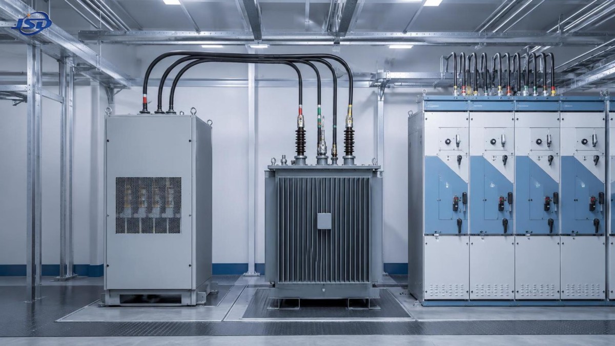
A grounding transformer creates a reference between the three-phase system and earth. It does not normally supply the main load. Instead, it establishes a neutral point that can be solidly grounded or connected through a neutral grounding resistor (NGR), reactor, or other grounding equipment. The chosen transformer connection determines how it reacts to zero-sequence current—the current component associated with line-to-ground faults and certain unbalanced conditions.
This is where a zig-zag unit becomes distinctive. Its winding arrangement divides each phase into two portions placed on different core legs and connected so that normal positive-sequence phase voltages largely cancel at the neutral path. During a ground fault, however, zero-sequence currents add constructively. The transformer therefore offers a low-impedance path for zero-sequence current without acting like a conventional load-serving transformer.
Situations where a zig zag grounding transformer is usually the better fit
A zig-zag connection is especially attractive when the application is fundamentally about grounding rather than transformation. It is commonly selected for delta systems that need a neutral reference but do not need a separate phase-to-neutral load supply.
1. A delta bus needs grounding, but no auxiliary low-voltage supply
Suppose a facility has a three-wire delta distribution bus feeding motor control centers, large drives, process equipment, and transformer-fed loads. There is no need for line-to-neutral utilization loads at the bus level. A zig-zag grounding transformer can create the required neutral point with a compact, purpose-built arrangement.
A wye unit may still be electrically viable, but it can introduce a transformer configuration that has more capability than the grounding duty requires. If the project does not need voltage conversion or a usable secondary supply, the zig-zag approach is often more direct and economical in terms of installed function.
2. The ground-fault current must be deliberately limited
In resistance-grounded systems, the goal is generally not to maximize fault current. The goal is to provide enough current for reliable relay operation while limiting equipment damage, arc-flash energy, and mechanical stress at the fault point. A zig-zag grounding transformer paired with a correctly sized NGR is a familiar solution for this duty.
The transformer’s grounding duty must be evaluated over the specified fault duration, such as 10 seconds, 30 seconds, or another project-defined interval. The resistor, transformer thermal design, relay pickup settings, and upstream protection philosophy must work together. Selecting the transformer solely on continuous kVA can be misleading because grounding transformers are frequently rated according to short-time fault duty rather than normal load service.
3. Continuity of process matters after the first ground fault
Some industrial processes cannot tolerate an immediate trip for every ground event. In mining, petrochemical processing, water treatment, paper production, and certain continuous manufacturing lines, high-resistance grounding may be used to alarm on a first fault and allow an orderly response. The grounding transformer provides the neutral reference that makes ground-fault monitoring meaningful.
In such systems, a zig-zag design can be advantageous because it is dedicated to zero-sequence performance. It supports a stable reference for protection and monitoring without being expected to carry a broad set of normal phase-to-neutral loads that could complicate the fault model.
4. Space and installation simplicity are important
Where switchgear rooms are tight, an appropriately designed zig-zag grounding transformer can be a practical choice because its purpose is narrow: create a neutral and carry the specified fault duty. It does not require a conventional secondary load arrangement when none is needed. The actual footprint still depends on voltage class, insulation level, cooling method, enclosure, resistor package, and fault-current rating, but the functional simplicity can reduce unnecessary equipment.
When a wye grounding unit may make more sense
The case for zig-zag is strong, but it is not automatic. A wye-connected grounding transformer or a conventional wye secondary may be the better engineering decision when the project needs more than a grounding path.
If line-to-neutral auxiliary loads must be supplied—such as control power, lighting, instrumentation, or service outlets—a wye secondary can offer a usable neutral-based voltage source. In that case, the transformer is doing double duty: it supports grounding while feeding intentional loads. A zig-zag transformer is not normally selected for that role.
Voltage transformation is another clear divider. A zig-zag grounding transformer does not provide conventional isolation and voltage conversion in the way a two-winding wye-delta or delta-wye transformer does. When a project needs to step voltage up or down between system sections, a wye-connected transformer arrangement may be necessary, with the grounding scheme designed around it.
There are also cases where existing system architecture already provides a wye neutral. For example, a solidly grounded wye source may make an additional grounding transformer unnecessary. Adding one without reviewing available zero-sequence paths can create protection coordination problems rather than solve them. Technical evaluation should always account for all connected transformers, generators, cable capacitance, and parallel sources—not only the bus under study.
A practical comparison: function before preference
The comparison should not be reduced to “zig-zag for industrial, wye for everything else.” Both can be engineered for grounding. The key distinction is whether the neutral is needed solely for fault performance or also as a working conductor for normal system loads.
Fault studies are the decision point, not a formality
Before selecting either arrangement, model the system’s line-to-ground fault behavior. At minimum, the study should identify the available fault current at the intended grounding point, the desired resistor current if resistance grounding is used, ground relay sensitivity, cable charging current, and the fault-clearing or alarm strategy.
Cable charging current deserves particular attention in extensive medium-voltage networks. Long cable runs, variable-frequency drive installations, and multiple feeder sections can contribute capacitive ground current. If the selected NGR current is too low relative to total charging current, detection can become unreliable and transient overvoltage performance may suffer. Conversely, selecting a higher grounding current simply to “be safe” may increase fault energy beyond what the equipment protection philosophy intends.
Grounding transformer impedance also matters. The transformer must carry the specified zero-sequence current while maintaining the expected neutral performance. A nameplate that appears adequate in kVA terms may still be unsuitable if its impedance, short-time thermal capability, insulation level, or neutral bushing arrangement does not match the grounding study.
Harmonics, unbalance, and the limits of simplified rules
A common assumption is that a zig-zag transformer automatically solves all harmonic problems. It does not. Its winding arrangement can provide a path for certain triplen harmonic components and zero-sequence currents, but harmonic behavior depends on the full network: nonlinear loads, filters, capacitor banks, cable lengths, converter topology, source impedance, and transformer connections elsewhere in the plant.
For systems with large rectifiers, UPS equipment, electric vehicle charging, or inverter-based energy assets, the grounding design should be reviewed alongside a harmonic assessment. The issue is not merely whether harmonics exist; it is whether they produce unwanted neutral currents, overheating, nuisance relay behavior, resonance, or distorted voltage references.
Temporary and mobile energy assets need the same discipline. A trailer-mounted battery system operating at a temporary construction site or emergency location may be connected to a generator, a local utility service, or an isolated load bus. For applications involving the 100kW/215kWh Mobile Trailer Energy Storage System, grounding arrangements should be checked against the operating mode of the 400 V AC output, the inverter’s neutral configuration, and any transfer equipment used between grid, solar PV, and diesel-generator charging sources. A grounding transformer is not automatically required, but a defined earthing and fault-protection strategy is essential whenever source configurations change.
Questions to ask before releasing the specification
- Is the source or bus delta-connected, ungrounded, impedance-grounded, or already solidly grounded?
- Do any loads require a phase-to-neutral supply, or is the neutral needed only for protection?
- What ground-fault current is required for relay detection, and for how long must the grounding equipment withstand it?
- Will the neutral be solidly grounded, resistance grounded, or reactance grounded?
- What are the network’s cable charging current and anticipated harmonic conditions?
- Are generators, parallel transformers, mobile power systems, or inverter-based resources able to create additional zero-sequence paths?
- What switchgear insulation level, enclosure type, ambient condition, and installation space must the equipment meet?
These questions often reveal that the transformer selection is really a protection coordination decision. The grounding transformer, NGR, current transformer placement, ground relay, and operating procedure should be treated as one engineered package.
Common selection mistakes
One frequent error is specifying a zig-zag unit without stating the ground-fault duration. “Neutral grounding transformer” is not enough information for manufacturing or evaluation. The required system voltage, grounding current, duration, connection, impedance expectations, insulation class, cooling arrangement, indoor or outdoor installation, and resistor interface should be clearly defined.
Another mistake is overlooking parallel grounding sources. A plant may add a generator, a second transformer, or a temporary power source years after the original installation. If each source provides a grounded neutral, ground-fault current can divide in unexpected ways. Protection that worked on paper for one source may become less selective after expansion.
Finally, avoid treating a grounding transformer as a generic accessory. It is a protective component with direct influence on fault energy, equipment stress, relay performance, and personnel safety. The correct design deserves the same review applied to switchgear ratings and protective-device coordination.
Making the final choice
Choose a zig zag grounding transformer when the system is three-wire or delta-connected, a stable neutral must be established, ground-fault current needs to be managed, and there is no requirement to serve routine phase-to-neutral loads. Its focused zero-sequence function makes it a compelling solution for resistance-grounded industrial and infrastructure distribution systems.
Choose a wye arrangement when the neutral must also support usable loads, when voltage transformation is part of the project, or when the existing system configuration naturally favors a conventional wye-connected transformer. In either case, the best answer comes from a coordinated review of fault studies, protection settings, source connections, and real operating modes.
Jinshida Electric Power Technology supports power distribution projects with engineering-focused equipment selection, manufacturing discipline, and practical attention to grid, industrial, new-energy, and infrastructure operating conditions. For evaluators, the most reliable outcome is not simply choosing zig-zag or wye—it is choosing the grounding method that behaves predictably when the system is under stress.

Get a Quote
Regardless of whether you require general advice or specific support, we are happy to help you.
Send Us Your Inquiry Today

Jinshida Electric remains committed to contributing to global energy development through professional manufacturing and superior service.