





Substation Transformer Maintenance: A Practical Schedule for Asset Managers
It is 7:20 on a damp Monday morning, and a site supervisor reports a sharp burnt-oil smell near the transformer bay. The load has not tripped, the gauges look almost normal from a distance, and production is waiting for a decision: keep the unit running, reduce the load, or shut it down for inspection. Situations like this are difficult because a substation transformer rarely fails without warning, yet the warning signs can be easy to dismiss when daily operations are busy.
A missed inspection can turn a small oil leak, blocked radiator, loose terminal, or cooling-fan fault into overheating, insulation damage, equipment outage, and a longer repair window. The practical answer is not simply “inspect more often.” A useful maintenance schedule gives each inspection a purpose, defines which findings need immediate action, and builds a condition history that helps the maintenance team distinguish normal aging from a developing defect.
Start with the operating conditions, not a generic calendar
A calendar-based plan is necessary, but it should not be the only basis for maintenance. Two units of similar age can require very different attention. One may operate in a clean indoor substation with stable loading; another may face dust, high ambient temperature, frequent load swings, coastal humidity, or intermittent overloads. Their maintenance priorities should not be identical.
Before setting intervals, collect the information already available: transformer rating, cooling method, insulation class, oil test history, loading profile, fault records, protection events, ambient conditions, and any changes to connected equipment. Pay particular attention to recent site changes. New motors, harmonic-producing loads, EV charging equipment, renewable generation, or battery storage can alter loading patterns and thermal cycling even when the average demand appears unchanged.
For a substation transformer, the best schedule combines routine observation with periodic testing and condition-triggered work. Routine tasks identify visible or audible abnormalities. Periodic tests reveal changes inside the tank. Condition-triggered actions respond to trends before those trends become failures.
Every shift or weekly walk-through: catch the obvious signs early
Frequent visual checks do not require a shutdown, but they should be done carefully and recorded consistently. A brief walk-through is especially useful after storms, high-load periods, switching operations, or work near the transformer enclosure.
During the walk-through, look beyond whether the transformer is energized. Check for oil stains around valves, gaskets, radiators, bushings, and the base of the tank. A fresh leak may be small, but falling oil level can expose insulation and reduce cooling performance. Note unusual sound, including increased humming, rattling fan guards, pump noise, or intermittent arcing sounds near terminals. Compare the current top-oil temperature and winding-temperature indication with the normal operating range for similar load and ambient conditions.
Also inspect the cooling system. Fans should start and stop according to their control settings, rotate freely, and remain free of dust buildup. On forced-oil or forced-air systems, verify that pumps are operating and that cooler valves are in the intended position. A transformer may carry load acceptably with one cooling component out of service, but that condition should not become invisible simply because no alarm has appeared.
Outdoor equipment deserves an enclosure and drainage check. Standing water, blocked cable trenches, corroded ground connections, damaged warning signs, and animal entry points all create conditions that can complicate later maintenance. Record both defects and “no abnormality found” observations. The value lies in comparing entries over time, not in producing a long report after a fault.
Monthly checks: verify instruments and supporting equipment
Once a month, take a more deliberate look at the devices that protect and monitor the transformer. Confirm that temperature indicators, oil-level gauges, pressure-relief indicators, cooling-control panels, and alarm contacts are readable and free from physical damage. If a gauge has stayed at exactly the same position for an unusually long period, do not automatically assume conditions are stable; verify that the instrument itself is functioning.
Review alarm and trip records, even if no outage occurred. Repeated fan-failure alarms, high-temperature warnings that clear quickly, or unexplained Buchholz relay indications may point to a control, wiring, or mechanical problem that needs follow-up. Check the condition of silica gel breather material where fitted. Saturated or discolored desiccant can allow moisture into the conservator system, increasing the risk of moisture contamination in the insulating oil.
Monthly reviews are also a good time to compare load, temperature, and cooling status. A rise in operating temperature at a similar load may indicate fouled radiators, reduced fan output, an oil circulation issue, high ambient temperature, or a change in internal losses. The goal is not to diagnose the cause from one reading. It is to recognize that the relationship between readings has changed.
Quarterly or semiannual work: test what cannot be seen
Visual inspections cannot show the full condition of insulating oil or internal paper insulation. Depending on voltage class, criticality, loading, manufacturer guidance, and site history, oil sampling may be planned quarterly, semiannually, or annually. Use clean sampling equipment and follow a consistent method. Poor sampling can introduce moisture or particles and make the laboratory result less useful.
Typical oil testing may include dielectric breakdown strength, moisture, acidity, interfacial tension, particle condition, and dissolved gas analysis. Each result has a different meaning. A single out-of-range value should be reviewed alongside previous samples, operating events, and sampling quality. For example, an increase in moisture may relate to breather condition, seal integrity, loading temperature, or sampling handling. Dissolved gas patterns may require more urgent review when they change rapidly or suggest thermal or electrical activity.
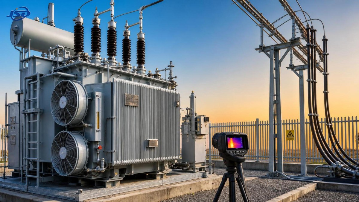
Thermal imaging should also be scheduled when the transformer is carrying a meaningful load. Scan bushings, cable terminations, jumpers, radiator connections, cooling motors, control cabinets, and nearby disconnects. A hot connection may result from loose hardware, oxidation, conductor damage, imbalance, or an undersized interface. The image is most valuable when it is compared with earlier scans under comparable load conditions.
Do not overlook grounding and surge protection. Inspect accessible grounding connections for corrosion, looseness, or mechanical damage. Examine surge arresters for cracked housings, contamination, abnormal leakage indications where applicable, and damaged leads. These components may not attract attention during normal operation, but their condition affects how the transformer responds to external electrical stress.
Plan an annual outage around meaningful tasks
An annual maintenance outage is often the only practical opportunity to perform de-energized inspections and corrective work. It should not become a rushed collection of unrelated tasks. Build the work scope from the previous year’s findings, pending defects, oil trends, protection records, thermal scans, and changes in operating duty.
Before isolation, confirm the approved switching procedure, lockout and tagging requirements, absence-of-voltage verification method, grounding arrangement, and communication responsibilities. The maintenance scope should clearly separate visual inspection, electrical testing, cleaning, mechanical tightening, functional checks, and work that requires specialist support.
With the transformer safely isolated, inspect bushings for cracks, chips, tracking marks, oil seepage, and contaminated surfaces. Clean only with materials and methods suitable for the bushing type. Examine cable boxes, gasketed covers, tap changer compartments, radiator valves, marshalling kiosks, and control wiring. Look for brittle insulation, loose glands, condensation, corroded terminals, or signs that rodents and insects have entered the cabinet.
Electrical tests may include insulation resistance, winding resistance, turns-ratio testing, excitation current testing, and power-factor or dissipation-factor measurements, as appropriate to the equipment and maintenance strategy. Test selection should follow site procedures, equipment condition, and technical guidance. Measurements are not useful in isolation; compare them with baseline values, prior records, phase-to-phase relationships, and temperature-corrected expectations where applicable.
Tap changers deserve focused attention because they are mechanical switching devices operating under demanding conditions. Whether the transformer uses an on-load or off-circuit tap changer, check its position indication, drive mechanism, interlocks, seals, contacts, and oil condition according to the relevant service instructions. Frequent voltage regulation activity may justify shorter inspection intervals than a stable installation.
When a finding changes the schedule
The most effective maintenance programs do not wait for the next planned date when evidence points to deterioration. Certain observations should trigger an earlier investigation: a noticeable rise in oil temperature at normal load, repeated cooling alarms, a new oil leak, increasing gas generation, abnormal bushing temperature, sudden noise change, pressure-relief operation, unexplained protection activity, or declining insulation test values.
Use a simple response path. First, confirm the observation and rule out instrument error or temporary operating causes. Second, compare the result with historical records. Third, assess whether the condition affects safety, dielectric integrity, cooling capacity, or ability to carry expected load. Finally, decide whether the unit can remain in service with increased monitoring, requires load reduction, or needs a controlled outage.
A common mistake is treating every abnormal value as either an emergency or a nuisance. Neither approach is reliable. A slowly changing trend may allow time to plan repairs and obtain parts. A fast change, even within a nominal range, can be more concerning than a stable value slightly outside a preferred target. Trend direction, rate of change, and operating context matter.
Load changes deserve a second look at transformer maintenance
Electrical systems are increasingly asked to manage more variable demand. When a site adds renewable generation, large charging loads, or energy storage, the transformer may experience different daily peaks and more frequent changes in current direction or magnitude. That does not automatically create a problem, but it does mean temperature and loading records should be reviewed after commissioning.
For facilities using an outdoor energy storage unit, scheduled review of transformer loading should include charging periods, discharge periods, backup operation, and any peak-shaving settings. A system such as the 125kW/261kWh Commercial & Industrial Energy Storage System can support peak shaving, load shifting, backup supply, and renewable energy integration. Its value in this context is operational: it may help a facility manage demand, but transformer protection settings, cable capacity, grounding, and thermal limits still need to be checked as part of the overall electrical design and maintenance plan.
After any significant load-management change, compare transformer temperatures and load profiles with the earlier baseline. Watch for unexpected peak loading, harmonic effects where non-linear loads are present, and cooling-system operation during the warmest part of the day. Update the maintenance record so that future inspections reflect the new operating pattern rather than the conditions that existed years earlier.
Make records useful when the next person opens them
A maintenance report should help someone understand the transformer’s condition in minutes. Include the date, equipment identification, loading condition, ambient condition if relevant, readings taken, defects found, photographs when needed, test reports, corrective actions, and unresolved items. Avoid vague notes such as “checked OK” when a measurement or specific observation could be recorded.
Keep a separate action log for defects. Each item should identify the condition, location, risk level, temporary control if any, recommended repair, responsible person, and target completion date. Once repaired, document how the repair was verified. This prevents minor issues from being carried forward indefinitely because they were mentioned in an old inspection report but never formally assigned.
A dependable substation transformer maintenance schedule is not a stack of forms. It is a working routine that connects field observations, test data, loading history, and repair decisions. When the schedule is adjusted to actual operating conditions, small warnings are easier to investigate, outages are easier to plan, and the transformer is less likely to become an urgent problem at the worst possible time.

Get a Quote
Regardless of whether you require general advice or specific support, we are happy to help you.
Send Us Your Inquiry Today

Jinshida Electric remains committed to contributing to global energy development through professional manufacturing and superior service.