





High Voltage Transformer Insulation: How to Assess Aging and Breakdown Risk
Insulation Condition Is a Reliability Decision, Not a Routine Test
For a technical evaluator, insulation assessment is rarely about proving that a transformer is either “good” or “bad.” The more useful question is whether the insulation system has enough remaining margin for its actual duty cycle, fault exposure, and expected service horizon. A high voltage transformer can remain operational while several degradation mechanisms are already progressing. By the time a conventional alarm appears, the decision may no longer be limited to maintenance planning; it may involve outage risk, replacement lead time, environmental exposure, and system contingency.
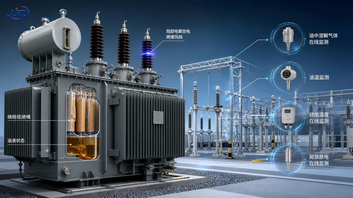
The insulation system includes more than transformer oil. In oil-filled units, mineral oil or ester fluid works together with cellulose paper, pressboard barriers, winding spacers, tap-changer insulation, bushings, lead insulation, and the interfaces between these materials. Aging in one part can accelerate deterioration elsewhere. Moisture in paper affects dielectric strength in oil; elevated temperature accelerates cellulose depolymerization; partial discharge can damage local interfaces long before a bulk oil test becomes unacceptable.
This is why a single laboratory result should not drive a major decision. Effective assessment combines test data, loading history, design information, operating environment, maintenance records, and trend analysis. The objective is to understand both present condition and the likelihood of breakdown under foreseeable electrical and thermal stress.
What Actually Ages Inside the Transformer
Cellulose insulation is usually the life-limiting material in an oil-filled power transformer. Oil can often be processed, dried, reclaimed, or replaced. Paper insulation inside windings cannot be practically renewed without major internal work. As cellulose ages, its polymer chains shorten, mechanical strength declines, and the insulation becomes less able to withstand vibration, through-fault forces, winding movement, or thermal cycling.
Heat, moisture, and oxygen are the principal drivers of paper aging. Their interaction matters. A transformer that operates moderately above its design thermal condition may age much faster than expected, particularly when moisture is already present in the paper. Oxygen ingress through conservator breathing, defective bladder systems, poor sealing, or inappropriate oil handling can further accelerate oxidation and sludge formation.
Oil deterioration follows a related but distinct path. Oxidized oil can develop acids, increased interfacial tension loss, sludge precursors, and higher dielectric losses. These conditions may impair cooling and create deposits on windings and ducts, causing local hot spots. The result can become self-reinforcing: poorer heat transfer raises temperature, and higher temperature drives faster insulation aging.
Electrical stress also has its own failure pathways. Partial discharge, switching surges, lightning impulses, harmonic distortion, transient overvoltage, and uneven voltage distribution can overstress weak areas. Bushings, tap changers, winding leads, sharp conductor edges, and contaminated interfaces often deserve focused attention because localized defects may not be visible in broad condition indicators until the defect has advanced.
Start with the Operating Context
Before selecting tests, evaluators should establish what the transformer has actually experienced. Nameplate rating alone is not enough. A 15-year-old unit that has operated at moderate, stable load in a clean indoor substation may have a very different insulation condition from an identical unit serving a variable industrial process, renewable plant, arc furnace, traction load, or constrained grid connection.
- Review load profiles, including seasonal peaks, overload events, and emergency loading periods.
- Identify major through-faults, external short circuits, protection trips, breaker failures, and transport or seismic events.
- Check ambient temperature, pollution level, humidity, coastal exposure, ventilation condition, and enclosure integrity.
- Confirm whether cooling equipment has performed as intended, including fan, pump, radiator, control, and alarm records.
- Examine changes in network configuration, grounding method, harmonics, switching frequency, and fault level.
- Compare recent gas, oil, moisture, and electrical test results with historical trends rather than isolated limits.
A recurring mistake is to interpret a test result without considering recent operational events. For example, elevated dissolved gases after a known overload may call for close follow-up, but not necessarily imply the same failure mode as a rapidly increasing gas pattern in an otherwise lightly loaded unit. Conversely, a result that remains within a generic guidance range can still be concerning when its rate of change is abnormal.
Oil Analysis: Valuable, but Not a Complete Diagnosis
Dissolved gas analysis remains one of the most useful tools for identifying active thermal or electrical faults in oil-filled equipment. Hydrogen, methane, ethane, ethylene, acetylene, carbon monoxide, carbon dioxide, and other gases can provide evidence of overheating, arcing, partial discharge, or cellulose involvement. The value lies in the gas pattern, concentration, generation rate, and operating context.
Technical teams should avoid treating gas-ratio methods as automatic fault verdicts. Ratio schemes can support interpretation, but gas behavior depends on transformer design, oil volume, oil preservation arrangement, sampling quality, load variation, and the stage of the fault. A small but rapidly increasing acetylene trend may be more significant than a higher stable background value. Similarly, carbon oxide gases should be assessed carefully: they can indicate cellulose overheating, but their interpretation requires awareness of oil age, oil processing history, and previous maintenance activity.
Oil quality tests add another layer of evidence. Common evaluations may include breakdown voltage, moisture content, acidity, interfacial tension, dielectric dissipation factor, resistivity, particle contamination, inhibitor condition, and furanic compounds. Not every test is needed at every interval, but the panel should match the asset’s criticality and suspected failure mechanisms.
Furan analysis is particularly important where paper aging is a central concern. Furans dissolved in oil can provide indirect information about cellulose degradation, although the relationship is influenced by oil replacement, oil reclamation, temperature history, design, paper type, and the distribution of aging within the winding. A low furan result after significant oil processing does not automatically mean that paper condition is healthy. It should be considered alongside moisture, carbon oxides, loading history, and, where justified, direct paper sampling during internal inspection.
Industry practice commonly refers to IEC and IEEE guidance for oil testing and gas interpretation, but applicable editions, contractual requirements, and local grid standards should be confirmed for the project. Thresholds and sampling intervals should be treated as decision aids, not as substitutes for engineering judgment.
Moisture Assessment Requires More Than an Oil Sample
Moisture is one of the most misunderstood insulation risks. Water concentration in oil changes with temperature, while most of the moisture mass in an aged transformer may reside in cellulose rather than oil. An oil sample taken at one temperature can therefore give a misleading impression if it is converted directly into paper moisture content without adequate operating data and model assumptions.
High moisture reduces dielectric margin, accelerates cellulose aging, increases bubble formation risk at elevated temperature, and can make short-term overload capability less defensible. The risk becomes especially important in units with high hot-spot temperatures, heavy cyclic loading, or limited cooling margin.
A stronger assessment combines laboratory moisture measurement with oil temperature at sampling, saturation calculations, historical trends, online moisture sensor data where available, and thermal loading information. If results indicate elevated paper moisture, the next question is not merely whether oil dehydration is possible. The team should determine the moisture source: atmospheric ingress, failed conservator protection, wet oil handling, insulation aging, inadequate drying after factory repair, or conditions associated with low-temperature operation and poor circulation.
Drying oil alone may provide only temporary improvement if the paper remains wet and the source of ingress is not corrected. For critical transformers, an outage-based dry-out plan may be justified, but its feasibility depends on transformer design, condition, site constraints, and the acceptable risk of thermal or vacuum treatment. This decision should be supported by the manufacturer or a qualified service provider rather than assumed from a single moisture result.
Electrical Tests Should Be Chosen for the Suspected Risk
Offline electrical tests can identify weaknesses that oil analysis may not reveal directly. The appropriate test package depends on voltage class, age, design, accessibility, previous findings, and outage opportunity. Broadly applying every available test can increase cost and may not improve the decision. The aim is targeted evidence.
Frequency response analysis deserves special attention after a significant through-fault, transportation event, or suspected winding displacement. Transformer windings can suffer mechanical movement while remaining electrically continuous. A unit may pass basic ratio and insulation resistance tests yet retain reduced mechanical withstand capability for the next fault event. Reference traces from factory acceptance testing or earlier field testing provide the strongest comparison basis.
Bushing assessment should not be treated as secondary. A substantial proportion of serious transformer failures involve bushings or their associated connections. Capacitance and dissipation factor trends, oil condition for oil-filled bushings, infrared inspection, leakage signs, porcelain or composite housing condition, and evidence of local heating all belong in the review. A good main-tank oil result does not eliminate bushing risk.
Partial Discharge: Do Not Wait for a Catastrophic Signal
Partial discharge is localized electrical activity that does not completely bridge the insulation gap. It can occur in voids, delaminated paper, contaminated surfaces, loose shielding, sharp electrode points, poor connections, or defective interfaces. Its significance depends on magnitude, repetition, location, phase relationship, and trend. A detected signal is not automatically an immediate failure condition, but unexplained or increasing discharge in a high-consequence asset should receive prompt engineering attention.
Online monitoring can be valuable for transformers exposed to high duty, critical service, or remote operation. Acoustic, electrical, ultra-high-frequency, and dissolved-gas-based approaches each have different strengths. The most credible diagnosis often comes from correlating more than one source. A partial discharge indication that coincides with gas generation, load-related behavior, and a consistent location estimate has greater decision value than an isolated signal in a noisy substation.
The practical issue is not whether monitoring replaces periodic testing. It does not. Monitoring improves visibility between outages, while laboratory testing and offline measurements provide deeper diagnostic evidence under controlled conditions. For critical assets, the two approaches should reinforce each other.
How Energy Storage and New Load Patterns Change the Assessment
Grid modernization is changing transformer duty cycles. Renewable generation, inverter-based resources, fast-changing industrial loads, and battery energy storage can introduce more frequent load transitions and different operating patterns from those assumed when older transformers were specified. These changes do not automatically shorten insulation life, but they make actual thermal behavior more important than annual average load.
For example, a commercial or industrial site that adds peak shaving or backup capacity may reduce sustained transformer loading while increasing the number of daily power transitions. Integration studies should examine transformer loading, harmonic performance, voltage regulation, protection coordination, grounding, and cooling response under charging and discharging schedules. Equipment such as a 500kW/1MWh Air Cooling Container Energy Storage System may support load management in these applications, but the upstream transformer assessment should include the resulting duty profile rather than assuming that storage always reduces asset stress.
Evaluators should request time-series data where possible. Fifteen-minute or shorter interval load data, ambient temperature, cooling stage operation, voltage profile, and harmonic measurements can reveal stresses that annual peak demand figures conceal. In many cases, this evidence is more useful for insulation-life planning than a generic statement that the transformer is “lightly loaded.”
From Test Results to a Defensible Action Plan
A condition assessment should end with decisions, not a stack of reports. Technical teams typically need to decide whether to continue normal service, increase monitoring, reduce loading, schedule maintenance, perform internal inspection, install online diagnostics, prepare a spare strategy, or begin replacement procurement. The choice depends on failure probability, consequence of failure, available redundancy, repair lead time, and confidence in the diagnosis.
It is useful to separate condition from criticality. A moderately aged transformer supplying a noncritical load with available backup may justify trend monitoring and planned intervention. The same condition in a constrained substation, process plant, data-intensive facility, or renewable export connection may require earlier action because the cost of an unplanned outage is far higher.
- Low immediate concern: stable oil and electrical trends, controlled moisture, no evidence of active fault, and adequate thermal margin. Maintain a disciplined baseline and review interval.
- Watch condition: gradual degradation, uncertain trend, elevated moisture, changed loading, or isolated diagnostic anomalies. Increase sampling frequency and define escalation triggers.
- High concern: rapidly increasing combustible gases, evidence of arcing or active partial discharge, significant bushing deterioration, suspected winding movement, or severe moisture and thermal exposure. Develop a risk-controlled outage and contingency plan.
There is no universal age at which a high voltage transformer becomes unacceptable. Well-managed units can remain reliable for decades, while younger units may deteriorate quickly after moisture ingress, inadequate commissioning, cooling failures, manufacturing defects, or repeated fault duty. Age is a useful screening factor, but it is not a diagnosis.
The strongest insulation decisions come from disciplined comparison: compare today’s data with the unit’s own history, compare actual duty with original assumptions, compare observed symptoms with plausible failure mechanisms, and compare intervention cost with the consequence of waiting. That approach gives technical evaluators a clearer basis for deciding whether an insulation issue is a maintenance item, a monitoring priority, or an emerging breakdown risk that cannot be deferred.

Get a Quote
Regardless of whether you require general advice or specific support, we are happy to help you.
Send Us Your Inquiry Today

Jinshida Electric remains committed to contributing to global energy development through professional manufacturing and superior service.