





SBH15 Amorphous Alloy Transformers: Ratings, Loss Limits, and Specification Checks
SBH15 Amorphous Alloy Transformers: Ratings, Loss Limits, and Specification Checks
For quality-control and safety teams, specifying an SBH15 amorphous alloy transformer is not simply a matter of selecting the right kVA rating. The nameplate capacity matters, but it does not show whether the unit will meet loss requirements, withstand the actual system voltage, remain thermally stable in service, or arrive with test records that match the approved specification.
This is especially relevant in distribution projects where transformers operate continuously at relatively light or moderate load. In that operating pattern, no-load loss can influence lifetime energy consumption more than many purchasing teams expect. An amorphous alloy core is intended to reduce that loss, but the claimed advantage should always be checked against the agreed rating, loss schedule, manufacturing tolerances, and test documentation—not assumed from the model designation alone.
An SBH15 amorphous alloy transformer is generally associated with an oil-immersed distribution transformer using an amorphous metal core. Exact configurations can differ by market, customer specification, voltage class, cooling arrangement, tap range, and applicable standard. The practical task is to convert the project requirement into a controlled inspection checklist before production starts, rather than trying to resolve missing details at factory acceptance.
Start with the ratings that define the duty
Capacity should be reviewed together with the installation profile. A transformer rated for a certain apparent power may be acceptable on paper but poorly suited to a site with high ambient temperature, restricted ventilation, harmonic-producing loads, repeated overloads, or unusual altitude. Quality teams should ask how the rating was derived: continuous duty, seasonal loading, emergency loading, or a network planning assumption. These are not interchangeable conditions.
The core nameplate items normally deserve direct cross-checking against the purchase order and approved drawings:
- rated power and cooling method;
- high-voltage and low-voltage rated voltages;
- system frequency, normally 50 Hz or 60 Hz as specified;
- vector group and phase displacement;
- tap changer type, tap positions, and voltage adjustment range;
- short-circuit impedance and its permitted tolerance;
- insulation level, including power-frequency withstand and impulse withstand requirements where applicable;
- temperature-rise limits, ambient assumptions, and insulation thermal class.
Short-circuit impedance is often treated as a minor line item, yet it affects fault current, voltage regulation, parallel operation, and protection coordination. A value that differs materially from the network study can change downstream breaker duties or make two otherwise similar transformers unsuitable for parallel service. It should be verified from routine test results, not copied from a catalogue page.
Voltage ratio and tap arrangement deserve the same attention. A site with persistently high incoming voltage may need a different tap setting from a site with long low-voltage feeders and substantial voltage drop. Confirm whether taps are off-circuit or on-load, who is authorized to change them, and what lockout procedure applies. An off-circuit tap changer must not be operated while energized.
Loss limits: compare like with like
The principal reason for choosing amorphous alloy technology is usually lower no-load loss. Conventional grain-oriented electrical steel and amorphous metal do not behave the same magnetically. The amorphous core can reduce magnetization loss, but it is also physically more sensitive during manufacturing and transport. Core clamping, annealing control, winding assembly, and mechanical protection all affect the finished result.
Loss evaluation should separate no-load loss from load loss. No-load loss is present whenever the transformer is energized. Load loss rises with current and includes winding resistance loss as well as additional losses caused by leakage flux. It is therefore misleading to select a unit solely because it has a low no-load-loss figure if the expected loading is high and the load-loss figure is not competitive.
A proper specification identifies the guaranteed maximum losses at the stated rated voltage, frequency, tap position, temperature reference, and test method. Those conditions matter. Load loss is commonly corrected to a stated reference temperature, while no-load loss should be assessed at the specified excitation condition. If one supplier presents values at a different temperature or voltage basis, the comparison is not valid until the figures are normalized according to the governing standard or agreed test procedure.
National efficiency requirements may apply in the destination market, and project documents may impose tighter limits than the minimum legal threshold. Standards and editions can change, so the procurement document should name the applicable edition rather than relying on a generic statement such as “latest standard.” For international work, IEC 60076 is frequently used as a technical reference series, but local grid codes, energy-efficiency rules, and utility specifications may add requirements.
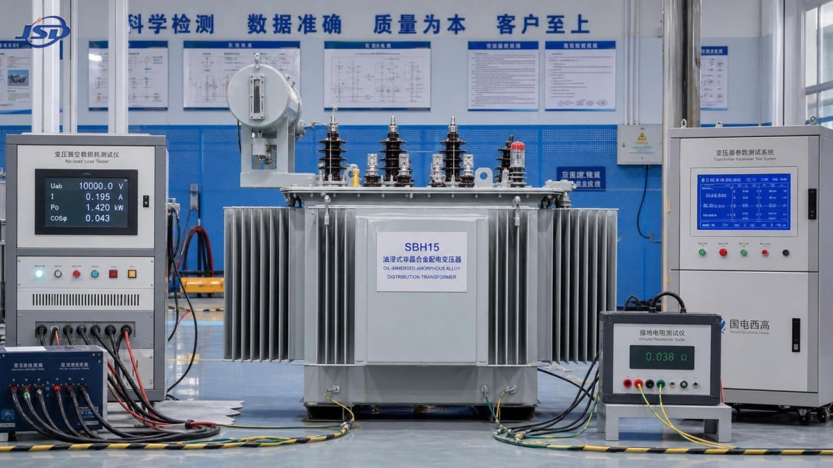
There is also a field reality worth noting: low loss is not a free pass on noise. Amorphous cores can have different magnetostriction characteristics and may require careful design to control audible sound. Where a transformer is near residences, schools, hospitals, or office space, ask for the contractual sound level and its measurement conditions. A promised decibel value without distance, background conditions, and load or excitation condition is not enough for acceptance planning.
Insulation, temperature rise, and safety margins
Transformer failures are rarely explained by one nameplate number. Insulation health depends on thermal stress, moisture, oil condition, electrical transients, workmanship, and the way the unit is connected and protected. For an oil-immersed distribution transformer, inspection should cover the winding insulation system, oil quality requirements, sealing arrangement, bushing condition, earthing points, and pressure-relief provisions where fitted.
Temperature-rise limits must be linked to the declared cooling mode and maximum ambient conditions. A compliant factory temperature-rise test does not automatically prove satisfactory field operation if the transformer will sit in an enclosed kiosk, a poorly ventilated substation, or a high-temperature industrial yard. Review the installation drawing early. Clearances, air movement, cable entry arrangements, fire separation, oil containment, and access for maintenance are safety items, not civil-work details to be decided later.
Dielectric withstand requirements should match the system’s overvoltage environment. Lightning exposure, cable network configuration, switching operations, and upstream protection philosophy can all affect the required insulation coordination. It is reasonable to request confirmation of the relevant dielectric tests, but do not assume that one voltage class has one universal set of withstand values across all applications. The approved technical schedule should govern.
What to check in the factory acceptance file
A credible factory acceptance process is not just a witnessed test day. It starts with document control. The manufacturer’s approved general arrangement drawing, nameplate schedule, wiring diagram, bushing layout, loss guarantee, and test plan should all use the same revision level. Small discrepancies—such as a changed tap range or a different vector group—can become expensive once cables and switchgear are already installed.
Routine test records generally need to demonstrate the agreed voltage ratio, winding resistance, vector group, impedance, no-load current and loss, load loss, and dielectric performance required by the applicable standard. Where special tests, type tests, or project-specific tests are requested, define them before the commercial order is finalized. A request made after the transformer has been built may require additional time, a different test setup, or may not be possible without redesign.
Review actual measured values against the guaranteed values and permitted tolerances. The review should include instrument traceability, test connections, ambient or oil temperature records where relevant, and any corrections used in the report. A test certificate that merely states “passed” is weaker than a record that allows an engineer to verify the result independently.
Visual inspection remains useful. Look for oil leaks, damaged paint, incomplete earthing labels, loose terminal hardware, unclear lifting marks, inadequate transport bracing, and inconsistent serial numbers across the tank, test report, and packing list. Amorphous alloy cores deserve particular care in transport handling because rough impact can affect mechanical stability and potentially alter sound or loss performance. Shipping instructions should be treated as part of the quality plan.
Protection interfaces should be reviewed as a system
A transformer cannot be judged in isolation from its protection scheme. Confirm the upstream and downstream protective devices, fault-level assumptions, surge arresters where required, neutral earthing arrangement, and the ratings of associated cables and switchgear. Protection settings should reflect the actual transformer impedance and inrush characteristics. Overly sensitive settings can create nuisance trips; settings that are too slow may allow damaging thermal or fault stress.
Backup generation creates another point of coordination. In facilities that need continuity of supply, such as hospitals, hotels, communication stations, schools, or residential communities, a transformer may operate alongside an emergency generator and automatic transfer equipment. The Silent Canopy Diesel Generator Set range is offered from 50kVA–500kVA prime power and 55kVA–550kVA standby power, with optional ATS and remote monitoring. For a quality review, the important issue is not the product label; it is whether generator voltage, frequency, neutral arrangement, fault-current capability, transfer sequence, and transformer protection settings have been coordinated as one installation.
A generator with a weather-resistant IP54 canopy and low-noise design may suit an outdoor backup installation, but its operating limits still need to be checked against site temperature, altitude, fuel autonomy, maintenance access, and local noise constraints. The same discipline applied to transformer ratings should apply to the complete standby-power path.
Questions that expose weak specifications early
Before release for manufacture, a few direct questions can prevent most avoidable disputes: Which standard and edition controls the design and tests? Are loss figures guaranteed maximum values or typical values? At what temperature and excitation conditions are they stated? What is the confirmed impedance tolerance? Which dielectric tests are routine, and which are additional? How will nameplate data, drawings, test certificates, and shipping records be linked to one serial number?
Manufacturers with established engineering, production, and quality-control processes are usually better able to answer these questions consistently. Jinshida Electric Power Technology Co., Ltd. focuses on power transmission and distribution equipment for grid construction, industrial manufacturing, new energy, and infrastructure applications. In practice, the useful measure of that capability is traceability: whether technical requirements remain controlled from design review through manufacturing, testing, delivery, and site support.
The best SBH15 amorphous alloy transformer specification is therefore not the longest one. It is the one that makes the duty clear, defines loss and insulation requirements on a common basis, identifies the governing tests, and connects the transformer to the protection and operating conditions around it. If those points are resolved before fabrication, acceptance becomes a technical verification rather than a negotiation over what the order was meant to include.

Get a Quote
Regardless of whether you require general advice or specific support, we are happy to help you.
Send Us Your Inquiry Today

Jinshida Electric remains committed to contributing to global energy development through professional manufacturing and superior service.