





Where Three-Phase Amorphous Alloy Transformers Fit in Commercial Distribution Systems
A commercial facility rarely experiences its heaviest electrical demand at a convenient time. An office tower may begin its morning start-up cycle while HVAC equipment is already running; a retail center may operate long hours with lighting and refrigeration carrying the base load; a logistics building may maintain controls, chargers, and security systems overnight. In these settings, the transformer remains energized even when much of the downstream load is light.
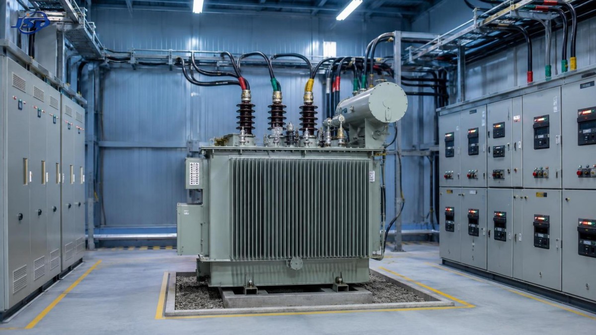
That operating pattern is where a three phase amorphous alloy transformer can fit particularly well. Its main value is not that it solves every distribution problem, but that it can reduce no-load loss in systems that stay energized for long periods. It is often a strong candidate for the main or secondary distribution transformer serving commercial loads with long annual operating hours, stable voltage requirements, and meaningful off-peak periods. The decision still depends on load profile, transformer location, capacity planning, harmonic conditions, and continuity requirements.
The first question is how long the transformer is energized at light load
Commercial distribution equipment is frequently selected around peak demand: the largest expected HVAC load, elevator demand, kitchen equipment, pumps, charging stations, or tenant expansion. That peak matters, but it is only one part of the operating picture. A transformer also consumes energy when it is energized and the downstream load is low. These no-load losses occur continuously while the transformer is connected to the supply.
Amorphous alloy cores are designed to lower core loss compared with conventional core materials. Therefore, they are usually most relevant where a transformer remains energized for many hours each day, including nights, weekends, holidays, and partial-occupancy periods. This makes the technology worth evaluating in commercial systems that have a relatively steady energized schedule even though the actual load rises and falls.
A building that is fully shut down outside working hours may see a different value balance from a site that must keep security, refrigeration, IT support, fire protection auxiliaries, common-area lighting, or critical controls operating around the clock. The useful comparison is not simply “commercial versus industrial.” It is the relationship between energized time, average loading, peak loading, and expected service life.
Where it usually fits in a commercial distribution layout
The most practical installation point is often at the boundary between the utility or medium-voltage supply and the building’s low-voltage distribution system. Depending on the project arrangement, that may be a pad-mounted transformer outdoors, a unit in a dedicated transformer room, or equipment feeding a main switchboard. A three-phase unit is appropriate when the downstream system supplies balanced three-phase loads as well as single-phase branch circuits.
Several application settings tend to justify closer review:
- Office and mixed-use buildings: These sites have long energized hours, changing occupancy, and substantial common-area electrical loads. The transformer may remain live well beyond normal tenant activity.
- Retail centers and supermarkets: Lighting, refrigeration, ventilation, point-of-sale systems, and security loads can keep the distribution system energized for extended periods. Loads may also be lower overnight rather than fully absent.
- Hotels and healthcare-related commercial facilities: Guest services, circulation areas, pumping, cooling, and operational support loads create a long-duration demand profile. Reliability planning is usually as important as loss reduction.
- Warehouses and logistics facilities: Even when dispatch activity varies, lighting, charging areas, controls, communications equipment, and security systems may maintain a continuous base load.
- Data-support and communications areas within larger properties: These spaces may require stable supply even while the rest of the building is lightly loaded. The transformer arrangement must be coordinated carefully with backup-power design.
- Municipal and infrastructure support buildings: Stations, service depots, pumping support buildings, and public facilities may combine long energized periods with variable daily use.
The technology can also be used in industrial-commercial campuses, but the loading pattern deserves more detailed review. A process facility with consistently high transformer loading may prioritize thermal performance, impedance coordination, motor starting behavior, and short-circuit duty alongside no-load loss. Amorphous-core construction is not a substitute for those checks.
Do not treat lower no-load loss as a complete selection rule
A common mistake is to choose solely on the assumption that lower core loss automatically makes one transformer the best commercial option. No-load loss is important, especially for continuously energized equipment, but it is only one part of total operating loss. Load loss rises as current increases and is influenced by conductor design, winding temperature, and actual loading. A transformer serving a heavily loaded electrical room may need to be assessed differently from one supporting a lightly loaded retail block.
The procurement review should separate the two loss components and compare them against the site’s expected load duration. It should also examine whether the proposed rating leaves sensible room for growth without becoming so oversized that the transformer spends most of its life at very low load. Oversizing is sometimes selected as a simple way to accommodate future tenants or added equipment, but it can increase capital cost and leave avoidable energized losses in place for years.
A better approach is to develop a realistic load picture. Gather interval demand data where an existing system is being upgraded. For a new facility, build the estimate from connected loads, diversity assumptions, operating schedules, and known expansion stages. Then distinguish the loads that are essential at all times from those that appear only during peak business activity.
Questions that reveal whether the application is suitable
- Will the transformer remain energized continuously, or can sections of the facility be isolated after hours?
- How often does actual demand remain far below the proposed transformer rating?
- Is capacity being added for a defined near-term load, or only as a precaution?
- Will tenant fit-outs, electric vehicle charging, larger HVAC equipment, or refrigeration add significant demand later?
- Are there nonlinear loads such as variable-speed drives, UPS equipment, LED drivers, or extensive IT loads?
- Does the distribution arrangement require a particular impedance range to coordinate protection devices and fault current levels?
These questions prevent the selection process from becoming a material comparison without a system context. They also help identify whether one larger transformer, multiple smaller units, or staged capacity would better match the way the property actually operates.
Voltage quality and harmonics still need separate attention
Commercial facilities increasingly use electronic loads. Variable-frequency drives control pumps and fans; UPS systems support sensitive equipment; LED lighting uses electronic drivers; chargers and power supplies add non-linear current to the network. An amorphous alloy core does not remove the need to assess harmonics, neutral loading, voltage distortion, or heating caused by these loads.
Before finalizing the transformer, the design team should identify the expected proportion of nonlinear load and the likely harmonic spectrum. The relevant transformer specification may need to address winding heating, derating requirements, shielding or electrostatic considerations, neutral capacity, and coordination with harmonic mitigation equipment. The right answer depends on the site rather than on a generic label.
Motor-driven systems require another practical review. Elevators, large air-handling units, chillers, pumps, compressors, and fire-protection equipment can introduce starting or transient demands. The transformer must support acceptable voltage performance during those events, while downstream protective devices must still coordinate correctly. A transformer that looks efficient in a basic comparison can create operating complaints if the design ignores starting conditions and feeder voltage drop.
Use the transformer as part of a continuity plan, not an isolated efficiency upgrade
Commercial distribution systems often need a response to utility interruptions as well as daily energy use. The transformer supplies normal power; it does not provide backup power during an outage. When continuity is required, the normal distribution path must be coordinated with emergency generation, transfer switching, essential-load panels, and any uninterruptible power systems.
For example, a property may place life-safety auxiliaries, critical communications, selected refrigeration, security systems, sump pumps, or business-critical servers on an essential bus. In that case, the transformer rating and distribution topology should be reviewed with the generator capacity, generator voltage, transfer sequence, and expected step loading. The goal is to avoid assuming that every normal load can or should be carried by the emergency source.
Where standby generation is part of the design, an Open Type Diesel Generator Set may be considered for industrial, commercial, agricultural, or construction-related backup arrangements where an equipment-room installation is appropriate. The available configuration includes three-phase, four-wire output, a 50Hz or 60Hz option, brushless excitation, electronic governing, and optional ATS compatibility. Its stated prime-power range is 50kVA–500kVA, with standby power from 55kVA–550kVA. Those figures should be matched to the defined essential load rather than to the entire normal-service transformer rating.
Generator and transformer coordination also requires attention to fault levels, grounding arrangement, neutral switching where applicable, inrush behavior, and protection settings. A backup generator can be correctly sized in kVA yet still perform poorly if large motor starts, transformer energization, or an improperly sequenced transfer causes excessive voltage or frequency disturbance. Critical loads should be prioritized and started in a planned order when the application requires it.
Installation conditions can change the practical choice
Transformer rooms are not interchangeable spaces. Indoor installations may be constrained by ventilation, fire separation, access routes, noise limits, maintenance clearance, and the need to keep equipment away from water ingress. Outdoor installations introduce other concerns: ambient temperature, enclosure suitability, corrosion exposure, drainage, access control, and vehicle protection.
Core material does not eliminate these site conditions. An efficiency-focused transformer still requires a suitable cooling environment and enough clearance for inspection, cable termination work, and safe isolation. The sound level should also be considered where the transformer is near offices, residences, hotel rooms, or occupied public areas. Noise issues are easier to address during layout planning than after the electrical room has been built around installed equipment.
In a multi-transformer arrangement, physical separation and distribution routing deserve particular care. The system may use separate transformers for different tenant areas, a dedicated transformer for sensitive loads, or parallel units to support capacity and maintenance objectives. Each approach has implications for load sharing, protection, bus ties, fault current, and the ability to keep part of the building energized during planned work.
A practical review before specifying the unit
The most reliable way to decide where a three-phase amorphous alloy transformer belongs is to begin with the single-line diagram and the load schedule, then test the proposal against real operating behavior. Confirm the primary and secondary voltage, frequency, vector group where required, kVA rating, impedance, tap arrangement, insulation and cooling requirements, installation type, and applicable local electrical rules. These are not administrative details; each one affects compatibility with switchgear, cables, protection, and operating procedures.
Next, identify the anticipated load curve. A facility with a low but persistent base load and periodic peaks may benefit from a different capacity strategy than a site that remains heavily loaded throughout production or trading hours. Verify demand assumptions with available records rather than relying only on connected load totals. Connected load can substantially exceed simultaneous operating load, while a new high-demand tenant can make an older estimate obsolete.
Finally, review maintainability. Distribution equipment should be selected with realistic access for inspection, cleaning, infrared checks, connection retightening, and future testing. A technically suitable transformer installed in an inaccessible room can turn routine service into a disruptive outage. Where continuity requirements are high, plan isolation points and sectionalizing arrangements before construction, not after a fault exposes the limitation.
Questions that often arise during planning
Is an amorphous alloy transformer only useful for low-load buildings?
No. It can be useful in buildings with moderate or changing loads because its main advantage relates to no-load loss while energized. However, a heavily loaded site still needs a full evaluation of load loss, temperature rise, impedance, harmonics, and peak-duty requirements.
Can it replace the need for energy monitoring?
No. Monitoring remains valuable because it shows whether demand assumptions are accurate, reveals unusual overnight loading, and helps identify whether future capacity is genuinely needed. It also supports better decisions about transformer loading and emergency-load prioritization.
Should normal and emergency loads use the same transformer capacity basis?
Not automatically. Normal-service capacity may include loads that are intentionally shed during an outage. Emergency generation and transfer equipment should be sized around the essential-load schedule, starting sequence, and permitted operating priorities.

Get a Quote
Regardless of whether you require general advice or specific support, we are happy to help you.
Send Us Your Inquiry Today

Jinshida Electric remains committed to contributing to global energy development through professional manufacturing and superior service.