





Metering vs. Protection: Configuring Indoor Current Transformers for Switchgear Panels
Accurate energy data and dependable fault response begin with separate decisions, even when both functions are installed in the same switchgear panel. A metering current transformer is selected to reproduce normal load current with controlled error. A protection current transformer is selected to remain useful when current rises far above normal during a fault. Treating these duties as interchangeable can produce a panel that records energy acceptably but delays relay operation, or one that protects the feeder while giving poor low-load measurements.
The starting point is the intended secondary circuit. Identify every meter, relay, transducer, analyzer, and test terminal connected to each core, then define the operating current range and the maximum fault level at the CT location. The ratio, accuracy class, rated burden, core quantity, and installation arrangement should follow that information. Selecting the CT from the primary conductor size alone leaves out the conditions that determine whether the secondary signal remains reliable.
Metering and protection stress a CT in different ways
Metering cores spend most of their service life around normal load. Their value lies in predictable ratio and phase performance over the current range used for billing, monitoring, power quality analysis, or load management. Low current performance matters when a feeder has long periods of light load, variable production, or standby operation. A CT that is adequate near rated current may still introduce an undesirable relative error when the actual current is a small fraction of its rated primary value.
Protection cores face a different electrical condition. During a short circuit or high inrush event, the relay needs a secondary current that still represents the primary event well enough to identify its magnitude and direction. If the CT core saturates too early, the relay sees a clipped or reduced waveform. The result may be delayed tripping, incorrect restraint behavior, or an event record that does not describe the actual fault.
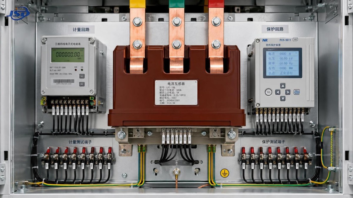
A multi-core indoor current transformer is often the cleanest arrangement when one primary conductor must serve both purposes. Each core then has its own class, burden rating, secondary terminals, and connected circuit. The physical housing may be shared, but the electrical duties remain separate. A single core should not be expected to serve a revenue-quality meter and a fast protection relay unless its documented characteristics explicitly meet both requirements under the actual connected burden.
Start with the ratio, then test it against real load behavior
The primary-to-secondary ratio should cover the expected continuous current without creating an unnecessarily small secondary signal at typical load. Oversizing the ratio is a common attempt to create future capacity. It can reduce resolution at low current, especially where a meter or transducer is expected to distinguish modest changes in a lightly loaded circuit. It may also cause a protection relay to receive a weaker secondary signal for lower-level faults, which can affect sensitivity settings.
Future expansion still matters, but it should be handled deliberately. Compare present maximum demand, credible expansion, conductor ampacity, breaker rating, and the protection study assumptions. A ratio selected only from the breaker frame can be misleading when the connected cable, transformer feeder, or process load limits normal current well below that value. Conversely, a ratio based only on present load can require replacement when the panel is uprated.
For circuits with widely varying current, consider whether the metering function needs a lower-ratio dedicated core, a dual-ratio CT arrangement where appropriate, or a meter input and CT specification designed for the required measurement range. The decision should be based on the lowest load that needs meaningful visibility, not merely on the largest current that might occur.
Burden is the complete secondary circuit, not a nameplate number
CT burden includes the connected device input, test switches, terminal blocks, interposing devices, and the resistance of both secondary leads. Long runs between a switchgear lineup and a remote protection or metering cabinet can consume a substantial part of the available burden. A device burden printed in volt-amperes does not describe the full circuit after copper lead resistance is added.
Secondary conductor size and route therefore belong in the CT calculation. Increasing lead length raises burden; reducing conductor cross-section does the same. Extra terminals added late for commissioning convenience also add resistance. These effects are especially important for protection circuits because the burden directly influences the voltage the CT must develop before saturation. A protection core that appears adequate at the relay input can become inadequate after the actual panel wiring is included.
Do not solve this by simply selecting the largest burden rating available. A metering CT may lose accuracy if the connected burden is far below or above the range for which its accuracy is declared. For protection, the required class performance must be evaluated at the real burden and fault duty. The practical target is a documented match between CT capability and installed circuit burden, with enough allowance for approved wiring changes but no reliance on undefined spare capacity.
Read accuracy class in the context of the duty
Metering classes describe permitted measurement error under specified conditions. Protection classes describe the CT's ability to supply current to a stated burden up to a defined multiple of rated current before its error exceeds the applicable limit. The labels may look similar on a datasheet, yet their meaning is different. A lower metering error designation does not automatically indicate better fault performance.
Protection applications also need attention to relay function. A simple time-overcurrent element and a sensitive earth-fault element do not place the same demands on the CT. Differential protection, high-impedance schemes, directional elements, transformer inrush restraint, and protection systems that must remain stable for through-faults require a more detailed review of saturation behavior, knee-point characteristics where relevant, remanence, and transient response. The protection coordination study supplies part of this information, but it must be translated into CT requirements rather than treated as a separate document.
Fault asymmetry deserves particular attention. The DC offset present at fault inception can drive a core toward saturation more severely than a symmetrical current value suggests. The location of the fault, system source impedance, breaker clearing time, and X/R characteristics affect this condition. A specification based only on symmetrical prospective fault current can leave an unexamined weakness in the relay measurement path.
Core allocation and polarity prevent avoidable commissioning problems
Each core should be allocated before the panel drawings are released. Terminal diagrams need to show the core designation, ratio, class, burden, polarity marks, secondary grounding point, test links, shorting facilities, and destination device. Labels on the CT, wiring drawings, relay configuration, and commissioning records must use the same identity. A core labeled for metering at the device end but landed on a protection circuit is not a minor documentation defect; it changes the basis of the design.
Polarity is equally important. For ordinary import metering, a reversed polarity may show negative power or produce incorrect energy direction. In directional protection, differential protection, and residual current arrangements, a single reversed CT connection can create unwanted operating current or block a genuine trip. The primary direction mark should be aligned with the agreed power-flow and protection reference direction before busbar or cable installation begins.
The CT secondary should have one controlled grounding point according to the panel scheme. Multiple earth points create parallel paths and can introduce circulating current or confusing test results. Leaving a CT secondary open while primary current is flowing is hazardous because a high secondary voltage can develop. Test blocks with shorting contacts should be selected and wired so a device can be isolated without opening an energized CT circuit.
Installation details affect electrical performance
An indoor current transformer must fit the actual switchgear geometry, not only the nominal conductor rating. Confirm the window dimensions or bushing interface, busbar spacing, insulation clearances, phase arrangement, mounting orientation, and terminal access. A physically forced installation can place stress on insulation, make secondary terminals inaccessible, or obscure polarity markings after the panel is assembled.
For busbar-mounted units, verify that the primary conductor is centered as intended by the manufacturer and that adjacent phase conductors do not pass through the sensing window or create unintended magnetic influence. Cable-mounted CTs require similar care: the complete phase conductor must pass through the aperture, while screen bonding conductors or parallel return paths must be routed in accordance with the protection scheme. Passing only part of a parallel conductor set through a CT produces a measurement that does not represent total feeder current.
Indoor does not eliminate environmental review. Condensation, dust accumulation, vibration, elevated enclosure temperature, and restricted cable bending space can affect long-term reliability and service access. Where a switchgear panel is associated with a wind generation collector system, the transformer and feeder arrangement may combine low-voltage turbine-side currents with medium-voltage collection circuits. The CT selection should follow the specific panel duty and fault study, even when the broader installation includes equipment such as a Transformer for Wind Power Generation with a 0.69 kV low-voltage side and higher-voltage grid connection.
Verify the installed circuit before energization
Commissioning should confirm more than ratio labels. Inspect the CT nameplate against approved drawings, verify each secondary circuit end to end, and confirm that meter scaling and relay CT settings match the installed ratio. Primary injection or another suitable functional test can validate phase association, polarity, current values, and expected relay or meter response. Secondary injection tests are useful for relay logic but do not by themselves prove the installed primary-to-secondary polarity or phase routing.
Record the actual secondary lead lengths, conductor sizes, terminal additions, and final device burdens when these differ from design assumptions. That record is valuable when protection settings are reviewed after a panel modification. Changes such as replacing an electromechanical meter with a digital analyzer, extending a cable route, or adding a second relay input can alter the burden enough to require a CT reassessment.
The most reliable configuration separates metering accuracy from protection survivability, then joins both to the actual wiring and system study. Ratio, class, burden, polarity, and installation geometry form one electrical arrangement. When they are reviewed together before fabrication and again after wiring, the indoor current transformer becomes a dependable measurement interface rather than an overlooked limitation inside the switchgear panel.

Get a Quote
Regardless of whether you require general advice or specific support, we are happy to help you.
Send Us Your Inquiry Today

Jinshida Electric remains committed to contributing to global energy development through professional manufacturing and superior service.