





Indoor Current Transformer Selection for Switchgear: Accuracy Class, Burden, and Ratings
An indoor current transformer should be selected from the protection and metering duties backward, not from the primary current rating forward. A unit that fits the busbar and has the correct ratio can still produce inaccurate billing data, fail to operate a relay as intended, or be damaged during a fault if its accuracy, burden, insulation, and short-circuit ratings do not match the switchgear application.
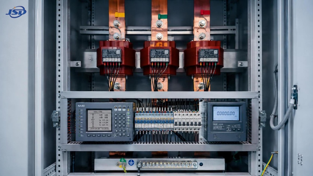
For switchgear evaluation, begin by separating each CT core by function: revenue or operational metering, indication, protection, power-quality monitoring, or a combination that has been intentionally verified. Then define the real secondary circuit, including every meter, relay, cable run, terminal block, and auxiliary device. This sequence prevents the common mistake of specifying a “standard” CT before understanding what it must drive.
Start With the Primary System and Installation Constraints
The current ratio must represent the expected operating range, not simply the maximum possible feeder current. For example, choosing an excessively large ratio for a lightly loaded feeder can reduce useful resolution at normal load. Conversely, a ratio that is too close to continuous operating current leaves little margin for load growth and may force an early replacement.
Review the following information before comparing catalog options:
- System voltage, frequency, grounding arrangement, and switchgear insulation level.
- Continuous feeder current, expected load profile, overload policy, and planned expansion.
- Available short-circuit current and the clearing time of upstream and downstream protection.
- Busbar dimensions, cable arrangement, CT window size, mounting position, and required clearances.
- Whether the CT is installed around a busbar, cable, bushing, or within a withdrawable breaker compartment.
- All secondary devices connected to each core and the approximate route length of secondary wiring.
“Indoor” does not remove environmental considerations. Switchgear rooms may still have high ambient temperature, condensation risk, dust, vibration, or restricted ventilation. A CT installed close to a heat-producing breaker or in a compact metal-clad compartment can face conditions quite different from those in a clean laboratory. The enclosure arrangement, insulation coordination, and manufacturer’s installation limits should be compatible with the actual panel design.
Accuracy Class Must Match the Duty
Accuracy class describes how closely the transformed secondary current represents the primary current under stated conditions. The correct class depends on what the connected device needs to do. Metering and protection are not interchangeable duties, even when both use a nominal 1 A or 5 A secondary circuit.
A metering core is intended to preserve measurement accuracy over its specified operating range and burden. It is appropriate for panel meters, energy meters, monitoring systems, and power-management equipment. The class should be selected according to the importance of the measurement. Billing, allocation between tenants, and internal energy accounting generally justify more careful accuracy and burden control than a basic local ammeter.
A protection core is selected to reproduce current sufficiently well for a relay during abnormal conditions. During faults, primary current can be many times normal current. If the CT saturates too early, the relay may see less current than is actually flowing or receive a distorted signal. That can affect relay sensitivity, coordination, and operating time.
One frequent specification error is requesting a very high metering class for a protective core, assuming it automatically improves protection. It does not. The relay needs a CT selected for the relay’s fault-performance requirements, not merely one with good normal-load metering accuracy. Where both duties are required, separate cores are often the clearer and more dependable arrangement.
Rated Burden Is a Secondary-Circuit Calculation
Rated burden is often treated as a nameplate detail, but it is a practical limit on what the CT can supply while maintaining its specified performance. The burden includes connected instruments or relays, secondary cable resistance, terminal blocks, test switches, transducers, and any other series-connected equipment.
The cable portion is commonly underestimated. Long secondary runs, undersized conductors, and unnecessary terminal connections increase burden. This is particularly important on low-current secondary circuits and on protection circuits, where cable resistance can materially influence CT behavior during high-current events.
The aim is not simply to choose the largest available burden. A CT should be selected with a rated burden that covers the calculated secondary burden with sensible margin, while remaining within the performance conditions expected by the connected devices. Overspecification can increase cost and physical size without solving a defined problem. Underspecification can compromise accuracy or protection response.
Calculate each core independently. A multi-core indoor current transformer may have one core for metering and another for protection, and each core has its own class and burden requirement. Do not combine the burden values across isolated cores.
Fault Ratings Are Not Optional Checks
Short-time thermal current indicates the level of fault current a CT can withstand for a stated short duration without unacceptable thermal damage. Dynamic current capability addresses the mechanical forces created by the fault’s peak current. Both must be considered against the fault duty at the installation point and the time required for protective devices to clear the fault.
A CT can be correct for normal current and still be unsuitable for the available fault level. This risk is greater in switchgear near transformer secondaries, bus couplers, generators, or parallel sources, where fault contribution may be substantial. System changes also matter: adding generation, changing transformer capacity, or altering bus-tie operating practices can increase the available short-circuit current after the original CT selection.
Protection applications require an additional question: does the selected CT maintain useful relay input through the relevant fault condition? The answer depends on CT class, ratio, burden, fault current, DC offset, and relay function. A catalog comparison alone is rarely enough for critical protection schemes; the CT data should be assessed alongside the relay application requirements.
Ratio and Secondary Current: Choose for the Whole Circuit
Common ratios such as 400/5 A or 800/1 A look simple, but the secondary choice affects the complete design. A 1 A secondary can reduce cable burden over long runs because the current-related losses are lower. It is often attractive when relays and meters are remote from the switchgear. A 5 A secondary remains common in established installations and may align with existing instruments, test equipment, and site practices.
The decision should be consistent across the connected equipment. Confirm that the meter, relay, transducer, test terminal, and commissioning tools all support the selected secondary current. A mixed assumption between 1 A and 5 A circuits can create a serious scaling error even when the wiring is otherwise correct.
Physical Fit and Insulation Coordination Need Early Attention
Switchgear CT selection is constrained by more than electrical data. Window dimensions must allow for the actual busbar or cable arrangement, insulation sleeving, phase spacing, and installation tolerance. A CT that barely fits on a drawing may be impractical to install after busbar joints, supports, or heat-shrink insulation are included.
Confirm the CT’s highest-voltage and insulation characteristics against the switchgear design. The relevant requirement is not the nominal operating voltage alone; the device must suit the insulation coordination of the assembly. This becomes especially important when equipment families are used across multiple voltage levels or when a panel is modified from its standard configuration.
Polarity and orientation deserve equal attention. Markings such as P1/P2 and S1/S2 establish the relationship between primary and secondary current direction. Incorrect polarity can reverse power readings, upset directional functions, or cause differential protection to behave incorrectly. Drawings should state the required orientation, and commissioning should verify it rather than relying on visual assumptions.
Where Energy Storage Changes the CT Discussion
Sites with bidirectional power flow need additional care. Battery energy storage, on-site generation, and controlled loads can change the direction and shape of feeder current. Metering may need to distinguish import from export, while protection may need directional elements or settings designed for multiple source conditions. The CT itself is not selected solely because energy storage is present, but the changing operating states must be included in the measurement and protection study.
For example, an industrial or commercial facility integrating a 125kW/261kWh Commercial & Industrial Energy Storage System may use the main switchboard CTs for load monitoring, demand management, and import/export visibility. The CT ratio and metering arrangement should capture both the usual site load and lower-current operating periods without losing useful data. Protection evaluation should also account for the system’s interconnection arrangement and whether reverse or parallel power flow is possible.
A Practical Specification Sequence
A concise, defensible CT specification usually follows this order:
- Define each measurement and protection function, then assign a dedicated core where the duties differ.
- Establish primary current from the present load profile, permitted overload, and credible expansion plan.
- Select the ratio and 1 A or 5 A secondary to suit both the connected equipment and cable distance.
- List every secondary-circuit component and calculate the burden for each core.
- Select the metering or protection accuracy class based on the actual device duty.
- Check thermal and dynamic fault withstand capability against the switchgear fault study.
- Verify insulation level, window size, mounting method, polarity orientation, and panel clearances.
- Place ratio, class, burden, fault ratings, terminal details, and test requirements on the drawings and procurement schedule.
The final procurement description should not rely on a short phrase such as “indoor CT, 800/5 A.” It should identify the required cores, ratios, secondary current, accuracy classes, rated burdens, insulation requirements, short-circuit withstand values, mounting arrangement, and any relay-specific performance expectations. Clear requirements reduce the chance that a supplier provides a physically compatible unit that is electrically wrong for the application.
Jinshida Electric Power Technology Co., Ltd. applies this system-level approach to transmission and distribution equipment: reliable current transformation depends on coordinated product design, manufacturing control, switchgear integration, and the operating conditions of the installation. For technical evaluators, that is the useful standard for comparison. The best choice is the CT whose defined performance remains suitable at normal load, during fault conditions, and after the system operates in the modes it was actually designed to support.

Get a Quote
Regardless of whether you require general advice or specific support, we are happy to help you.
Send Us Your Inquiry Today

Jinshida Electric remains committed to contributing to global energy development through professional manufacturing and superior service.