





Medium Voltage Transformer Selection for Commercial and Manufacturing Facilities
A medium voltage transformer is not a line item to finalize after the building load is estimated. In a commercial complex or manufacturing plant, it sets the limits for reliability, expansion, protection coordination, and energy loss for years to come. The right selection starts with the actual electrical behavior of the facility, not simply its connected load or the transformer size used on a previous project.
The practical objective is straightforward: choose a unit that matches the utility supply, handles normal and abnormal operating conditions, fits the installation environment, and leaves room for justified growth without paying for unnecessary capacity. That requires a few decisions to be made in the right order.
Start With the Load, Not the Nameplate
Many early specifications begin with a total connected load. This is useful, but it is not the transformer rating. Motors, HVAC systems, welders, compressors, data equipment, lighting, and process lines do not all operate at full demand at the same time. A facility with a large connected load may have a much lower measured maximum demand, while a plant with a modest connected load may create severe short-duration peaks during production starts.
A sound load study should review at least four things: present peak demand, expected load factor, power factor, and the load profile over a normal day or production cycle. Meter data is preferable for an existing site. For a new facility, the electrical design team should build a demand schedule based on equipment duty, diversity, and the startup characteristics of major motors.
Motor-heavy facilities deserve particular care. A transformer can appear adequately sized during steady operation yet experience unacceptable voltage dip when several large motors start. Soft starters, variable frequency drives, sequencing controls, or a revised transformer impedance may be more effective than simply selecting a much larger unit.
A useful decision rule is this: size for the expected operating demand and credible growth case, then verify thermal performance and voltage regulation under the worst realistic duty cycle. Do not size solely from a sum of equipment nameplates, and do not assume a large margin automatically solves power-quality problems.
Match the Medium Voltage Transformer to the Supply System
Voltage ratio is the obvious starting point, but it is only one part of compatibility. Confirm the utility nominal voltage, permitted supply variation, system frequency, grounding arrangement, and available fault level at the point of connection. The transformer primary rating, tap range, vector group, and insulation level must work with that specific network.
Tap selection is often treated as a procurement detail. It should not be. If the incoming utility voltage tends to run high or low, a fixed off-circuit tap setting may be enough. If the downstream bus must remain within a tighter voltage band while supply or load changes materially, an on-load tap changer may be justified. The correct choice depends on the network study, operating philosophy, and maintenance capability. An on-load tap changer adds control flexibility, but it also introduces equipment that must be inspected and maintained properly.
The secondary voltage must also reflect the actual distribution architecture. A transformer feeding a low-voltage main switchboard has different needs from one feeding a medium-voltage motor lineup, a rectifier system, or a dedicated process substation. In multi-transformer systems, vector groups and phase displacement must be coordinated before parallel operation is considered. Similar kVA ratings alone do not make transformers suitable for paralleling.
Short-circuit impedance is another specification that should be reviewed early. Lower impedance can improve voltage regulation but may increase available fault current downstream. Higher impedance can help limit fault duty but can create a greater voltage drop during heavy load changes. There is no universally “best” percentage impedance; it has to fit the protection study, switchgear ratings, motor-starting requirements, and cable lengths.
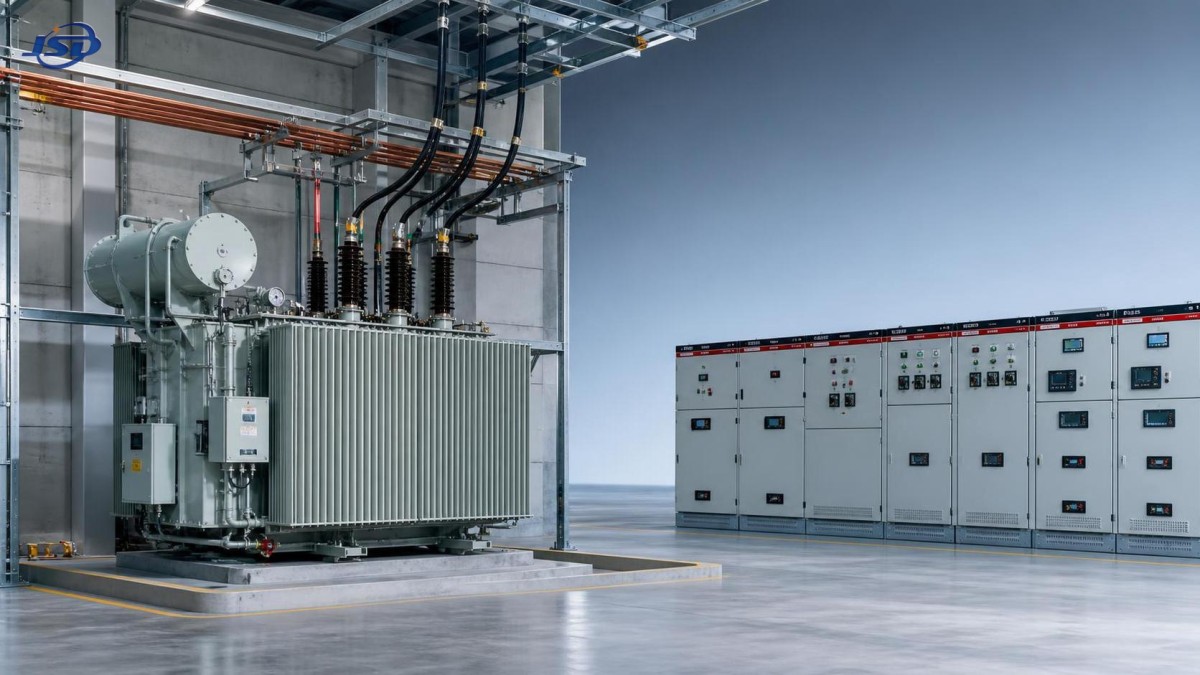
Dry-Type or Liquid-Filled: Choose for the Site Conditions
The dry-type versus liquid-filled decision is often framed as a simple safety comparison. In practice, location and operating conditions matter more than general preference.
Dry-type transformers are commonly selected for indoor installations where fire risk, ventilation, access, and building integration are central concerns. They avoid insulating liquid, but they still require appropriate clearances, airflow, temperature control, and cleaning. Dust accumulation, corrosive contaminants, and restricted ventilation can shorten service life or force derating. In a processing area with airborne fibers, metal particles, chemicals, or high ambient temperatures, “indoor” does not automatically mean “easy environment.”
Liquid-filled units are often favored for outdoor substations, higher capacities, or applications where compact design and thermal performance are priorities. Their installation requires attention to containment, fire protection, environmental requirements, and local authority rules. The liquid type also matters. Mineral oil, natural ester fluids, and other insulating liquids have different fire, environmental, and performance characteristics. The final choice should align with site requirements and applicable standards rather than a generic assumption about one technology being better.
For either design, ask the manufacturer to state the rated ambient conditions, allowable altitude, temperature-rise assumptions, enclosure or tank protection level, and any derating required for the proposed location. These details are especially important in hot climates, coastal installations, elevated sites, and enclosed electrical rooms.
Reliability Is Designed Into the Whole Distribution Scheme
One larger transformer may be less expensive to buy and install than two smaller units. It may also create a single point of failure. That tradeoff needs to be visible before the project is locked in.
For a warehouse with limited critical load and an acceptable outage window, a single-transformer arrangement may be entirely reasonable. For a continuous manufacturing process, a hospital-related commercial development, a large chilled-water plant, or a facility with expensive restart consequences, redundancy may be worth more than the apparent savings from a simpler arrangement.
N+1 capacity, split buses, tie breakers, sectionalized substations, and standby generation can all improve resilience, but they solve different problems. A standby generator may support essential loads but not an entire production process. Two transformers with a bus tie can offer maintenance flexibility, but only if the protection scheme and available fault duty are designed for the tie-closed and tie-open conditions.
Protection coordination should therefore be developed alongside transformer selection. Relay settings, fuse ratings, inrush restraint, differential protection where applicable, ground-fault protection, and downstream breaker ratings need to be considered as one system. A transformer that passes a basic datasheet review can still cause operational difficulty if its inrush behavior or impedance was ignored during protection design.
Energy Losses Need a Lifecycle View
Purchase price is visible in the tender. Losses are paid gradually through every operating hour. Core loss occurs whenever the transformer is energized, while load loss rises with current. A facility operating near full load for long production shifts will value the load-loss figure differently from a lightly loaded commercial site energized around the clock.
Comparing transformer efficiency only at one load point can be misleading. Request guaranteed no-load loss, load loss at the stated reference temperature, impedance, and expected efficiency across the anticipated operating range. Then use the facility’s expected annual load profile and local energy cost assumptions to compare lifecycle cost. The calculation should be transparent enough that the design team can challenge the assumptions.
Oversizing is a common response to future-growth uncertainty. It can be sensible where expansion is highly likely, but a significantly oversized transformer may spend years carrying light load while incurring avoidable no-load losses. A modular substation plan, space for a future transformer, or a dual-transformer arrangement may provide a better balance in some projects.
Harmonics, Power Quality, and Modern Loads
Facilities now contain more non-linear loads than many older transformer specifications assumed: variable frequency drives, UPS systems, EV charging equipment, LED drivers, welding equipment, rectifiers, and power conversion systems. These loads can introduce harmonic currents that increase heating in windings, leads, and neutral conductors.
The correct response is not to request a “harmonic transformer” without defining the load. Obtain the expected harmonic spectrum from major equipment suppliers or conduct measurements at an existing site. The transformer supplier can then assess thermal capability and propose suitable design measures. Depending on the application, the solution may involve a derated rating, a dedicated transformer, an appropriate vector group, filters, or changes to the load arrangement.
Industrial parks and microgrids require an additional check when battery storage is included. A containerized system such as the 1MW/2MWh Liquid Cooling Container Energy Storage System can change the power flow at the point of connection. Its PCS operating mode, fault contribution, control response, and voltage range should be reviewed with the transformer, protection, and utility-interface design. Storage can reduce peaks or support renewable integration, but it does not remove the need to validate transformer loading in charging, discharging, and bypass conditions.
Specifications That Prevent Late-Stage Problems
A concise but complete technical specification reduces ambiguity between bidders. It should state the required rating, voltage ratio, frequency, tap arrangement, vector group, impedance target or acceptable range, cooling class, insulation requirements, temperature rise, installation location, ambient conditions, altitude, sound limits where relevant, and applicable standards.
It should also define the test and documentation requirements. Routine test reports, nameplate details, dimensional drawings, terminal arrangements, losses, impedance, accessory list, wiring diagrams, and installation instructions should be available before shipment. For critical projects, witness testing or additional type-test evidence may be appropriate, subject to the project specification and local requirements.
Physical interfaces are easy to overlook until construction is advanced. Check transport weight, lifting points, access route, foundation loading, cable entry direction, termination space, clearances for doors and radiators, ventilation path, and maintenance access. A transformer that fits on a layout drawing may still be difficult to replace or service if cable trenches, walls, or overhead structure restrict access.
Questions to Resolve Before Placing an Order
Before final approval, the design team should be able to answer these questions clearly:
- What is the measured or calculated maximum demand, and what future load is genuinely committed?
- Can the transformer withstand the expected motor starts, harmonic load, and ambient conditions without unacceptable heating or voltage dip?
- Does its impedance keep downstream fault current within the switchgear and protection design limits?
- What outage consequence is acceptable, and does the single-line diagram provide the required level of continuity?
- Are the utility requirements, local codes, fire provisions, and site environmental conditions documented?
If those answers are vague, the specification is not ready. The most expensive transformer selection errors usually begin as unresolved assumptions between civil, electrical, utility, and operations teams.
Working With a Supplier Beyond the Datasheet
A reliable supplier should be willing to discuss the operating duty behind the rating, not just quote the requested kVA. This is where engineering support has practical value: checking losses against the load profile, reviewing vector-group compatibility, confirming accessory needs, and identifying installation constraints before fabrication.
Jinshida Electric Power Technology Co., Ltd. supports power transmission and distribution projects through transformer and power equipment development, manufacturing, and application support. For commercial, industrial, renewable, and infrastructure work, the useful conversation should begin with the single-line diagram, load data, site conditions, and required standards. A rigorous quality process matters, but it is most effective when the equipment design is based on complete project information.
The final medium voltage transformer decision should balance electrical performance, maintainability, resilience, and lifecycle cost. Select the unit that fits the actual system and credible future operating plan, then document the assumptions. That approach gives the facility a far stronger foundation than choosing the largest rating available within the initial budget.
Common Questions
How much spare capacity should be included?
There is no fixed percentage that suits every site. Use committed expansion plans, not vague optimism. Where future load is uncertain, allowing physical and electrical provision for a second transformer can be more efficient than heavily oversizing the first unit.
Can two transformers operate in parallel?
Yes, but only after checking voltage ratio, vector group, impedance, tap position, phase relationship, rating balance, and protection coordination. Parallel operation should be designed, not assumed.
Is a dry-type transformer always the safer indoor choice?
It is often appropriate indoors, but ventilation, dust, corrosive atmosphere, clearance, and local fire requirements still govern the final installation. Dry-type construction does not remove the need for site-specific review.
When should harmonic loading be investigated?
Investigate it whenever major drives, rectifiers, UPS systems, charging equipment, or other power-electronic loads form a meaningful part of the load. Waiting until overheating or nuisance trips appear is late and costly.

Get a Quote
Regardless of whether you require general advice or specific support, we are happy to help you.
Send Us Your Inquiry Today

Jinshida Electric remains committed to contributing to global energy development through professional manufacturing and superior service.