





Industrial Battery Storage Sizing Guide for High-Load Manufacturing Sites
Battery storage for a high-load plant should be sized from the electrical behavior of the site, not from a generic kWh target. The first question is whether the system is intended to shave demand peaks, hold critical loads through upstream disturbances, stabilize fast process loads, or bridge transfer time between utility supply and on-site generation. Each purpose drives a different ratio between power rating, energy capacity, transformer loading margin, inverter response time, and allowable depth of discharge. A system that looks adequate on a daily energy chart can still be undersized if the plant has short, steep current rises from large motor starts, welders, induction heating, compressors, or cyclic process lines.
For most industrial battery storage evaluations, the load profile needs to be split into layers. The base load is the continuously energized demand that remains relatively stable. Above that sits the process load, which may change by shift, batch, or machine state. A third layer often appears as transient or intermittent demand, where the duration is short but the power level is high. If these layers are not separated, the storage system is often oversized in energy and underspecified in discharge power. A battery may hold enough kWh for an hour and still fail to support a ten-second event if the inverter, busbar, cable set, or transformer impedance limits the actual power delivery.
When reviewing interval data, high-load sites should avoid relying only on utility billing peaks. Those peaks are useful for demand-charge analysis, but they do not describe internal bus conditions. Sub-second or second-level monitoring is often needed when the plant includes variable frequency drives, furnace transformers, large rectifier loads, or repeated inrush conditions. In many cases, the practical sizing exercise starts by marking three operating windows: normal production, constrained utility supply, and contingency mode. The battery is then sized against the worst credible condition within each window rather than against annual average consumption.
Start with the electrical boundary
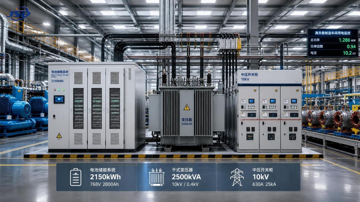
The point of connection matters. A battery installed on the low-voltage side of a distribution transformer behaves differently from one tied into a medium-voltage bus through a dedicated step-up transformer. On the low-voltage side, the system may directly support downstream feeders and sensitive loads, but conductor size, switchgear interrupt ratings, and voltage drop become immediate constraints. On the medium-voltage side, a larger section of the plant can be supported, yet transformer losses, protection coordination, and switching sequences become more complex. Sizing cannot be separated from this boundary because the transformer is not just a passive link; its impedance, thermal class, tap setting, and overload behavior affect the battery’s usable performance.
In transformer-centered designs, one common sizing error is to compare battery inverter rating with nominal transformer kVA only. That misses reactive power behavior, harmonics from power electronics, and existing loading margin at elevated ambient temperature. A transformer that appears to have spare capacity may already be operating near its thermal comfort zone during afternoon production, especially if ventilation is limited or harmonic content is significant. In that case, adding bidirectional power flow from battery charging and discharging can shift losses in ways that require a different transformer selection, a dedicated auxiliary transformer, or revised charging windows.
Another boundary issue is fault contribution. Battery inverters typically limit fault current compared with synchronous generation, but they still alter protection behavior. If the plant depends on selective tripping across several feeder levels, the protection study should be updated before finalizing capacity. A storage block that is electrically large but poorly coordinated may create nuisance trips during feeder faults or transfer events, which defeats the value of backup support.
Power rating usually decides the first pass
At manufacturing sites with concentrated machinery, the first sizing pass is often driven by kW or kVA rather than kWh. Peak shaving requires enough instantaneous discharge to clip the top of the demand profile. Backup support requires enough power to carry the selected loads without violating voltage tolerance or inverter overload limits. If the intended protected load includes motor groups, the sizing review should distinguish between running current and starting current, and between across-the-line starts and controlled starts. A battery that can sustain the steady-state load may still need help from soft starters, VFD logic changes, or staged restart sequences after an outage.
For short-bridge applications, where storage covers the interval before another source takes over, the duration may be modest while the power demand remains high. In that situation, energy capacity should not be padded without reason. Oversizing energy can increase footprint, thermal management burden, and replacement cost without improving the actual ride-through result. A smaller energy block with a stronger inverter section may be the better fit if the load transfer sequence is well defined.
That is also where another source may sit alongside storage in the power architecture. During longer outages or fuel-secure backup planning, some sites pair battery support with a generator path such as Silent Canopy Diesel Generator Set, using the battery to absorb transfer disturbances, carry fast load steps, or prevent low-load generator operation during variable production demand. In those arrangements, battery sizing should reflect the handoff logic rather than assuming it must independently cover the entire outage period.
Energy capacity depends on duty, not on nameplate arithmetic
After the power envelope is defined, the energy calculation can be built from actual duty cycles. A useful approach is to map each target scenario as a time sequence: pre-event state of charge, event duration, recharge window, and any repetition within the same shift. The required nominal capacity then has to be adjusted for reserve margin, minimum state of charge, degradation allowance, ambient temperature effect, inverter efficiency, transformer loss, and cable loss. Nameplate kWh is never fully available at the AC bus.
Depth of discharge should be selected from expected operating frequency. A battery intended for occasional contingency support can often use a different reserve strategy from one that shaves peaks every day. If the daily operating window is tight and recharge opportunities are limited, keeping too much reserve may force a larger system than necessary. On the other hand, using nearly the full available window can accelerate aging or reduce response confidence late in the service interval. The right balance depends on the plant’s tolerance for reduced autonomy near end of life.
Chemistry selection influences this margin. Lithium iron phosphate is often considered where thermal stability and cycling behavior are priorities, while other chemistries may be reviewed if space, discharge behavior, or temperature envelope point in a different direction. The selection should be grounded in enclosure design, ventilation, fire segregation, auxiliary loads, and maintenance practices, not only in cell-level specifications. HVAC consumption, cabinet heaters in cold conditions, and battery management standby demand all reduce net usable energy and should be included in the sizing basis.
Load selection has to match process reality
Plants rarely need every load backed by storage. Separating critical, deferrable, and nonessential circuits usually improves sizing accuracy more than any spreadsheet refinement. However, this split has to reflect process dependencies. A feeder that seems noncritical in isolation may support cooling water, lubrication, extraction fans, control air, or network switches required to keep another process line alive. Likewise, some loads cannot simply be dropped because restart scrap, thermal soak loss, or line cleaning time may be more disruptive than a brief electrical interruption.
For that reason, single-line diagrams should be reviewed alongside process interlock charts and sequence narratives. The battery design team needs to know which contactors must remain closed, which PLC racks must ride through without reboot, and whether certain transformers must stay energized to avoid long magnetizing or synchronization delays. This is particularly relevant where the facility has furnace transformers, rectifier transformers, or dedicated machine transformers that serve tightly coupled production equipment.
Feeder diversity also deserves attention. If the selected critical loads are distributed across several boards, the battery point of interconnection may force energy through multiple transformer stages or long cable runs. That can produce local bottlenecks even when total site capacity appears sufficient. It is often better to support a smaller but electrically coherent section of the plant than to claim broad coverage through a fragmented network with many transfer points.
Transformer integration changes the practical size
In industrial battery storage projects, the transformer is part of the sizing exercise in four ways: voltage matching, thermal loading, impedance behavior, and harmonics. Voltage matching is straightforward in concept but can become restrictive when the site has nonstandard utilization voltages or several transformer zones with different tap positions. Thermal loading becomes critical if charging overlaps with production peaks. A battery that charges aggressively after each discharge cycle may shift demand into a period where the transformer already runs warm.
Impedance behavior matters during fast discharge events. If the transformer impedance is high relative to the load step, the battery may not hold downstream voltage inside the tolerance required by sensitive drives or automation systems. Harmonics should be assessed from the inverter and from existing nonlinear loads. Additional filtering or a transformer with suitable K-factor considerations may be appropriate depending on the harmonic spectrum and thermal impact.
Isolation and grounding arrangements should also be reviewed early. The transformer connection group, neutral treatment, and earthing philosophy affect ground-fault detection and common-mode behavior. Problems in this area tend to surface late, often during commissioning, when correction is more difficult. A properly sized battery system can still underperform if grounding and protection logic were treated as secondary details.
Physical installation limits often remove theoretical options
Space, transport path, and maintenance access can narrow the battery choice before final selection. Containerized systems may simplify delivery but require crane access, foundation checks, and clearance for doors, fire separation, and cooling airflow. Indoor cabinet systems may fit an existing electrical room, yet room temperature, ventilation route, floor loading, and egress provisions need to be verified. If the site is in a corrosive, dusty, high-vibration, or high-humidity environment, enclosure rating and filter maintenance become part of the sizing decision because they affect thermal stability and service continuity.
Installation sequence matters as well. If the transformer, switchgear modification, and battery container arrive under different packages, temporary outage windows must align with bus tie work, protection testing, and control integration. A design that looks efficient on paper may become impractical if it requires multiple shutdowns of production feeders. In those cases, a modular battery configuration with staged energization can reduce commissioning risk, even if the final layout is less compact.
Common misjudgments in storage sizing
One recurring mistake is using average load for backup sizing. Average load hides short process spikes and auxiliary equipment that starts only during disturbances. Another is treating inverter efficiency as a fixed value across all operating points. Partial-load operation, temperature, and reactive power support can change the effective AC output available to the plant. A third is ignoring recharge constraints. If the plant has repeated peak events within the same shift, the battery must recover enough state of charge between them without creating a new demand peak through charging.
There is also a tendency to assume the same design margin should cover all uncertainty. In practice, uncertainties are different in nature. Some belong in electrical design margin, such as wiring loss variation and transformer temperature rise. Others belong in operational scenarios, such as one more restart attempt after a trip or an unexpected overlap of production loads. Separating these uncertainties makes the final capacity easier to justify and usually avoids inflated sizing.
Before release, the proposed size should be tested against a few harsh but credible operating sequences: partial utility sag during full production, battery discharge followed by immediate reclose attempt, and loss of a major feeder with downstream transfer logic active. If the system remains coherent under those conditions, the selected capacity is usually grounded in the actual plant rather than in catalog assumptions.
A sound sizing result is the one that survives the electrical details: transformer behavior, feeder topology, discharge power, recharge limits, and the real order in which industrial loads start, stop, and recover.

Get a Quote
Regardless of whether you require general advice or specific support, we are happy to help you.
Send Us Your Inquiry Today

Jinshida Electric remains committed to contributing to global energy development through professional manufacturing and superior service.