





How to Specify a Power Plant Transformer for Reliable Unit Operation
During the final design phase of a generating unit, transformer selection often appears to be a straightforward equipment task: confirm the generator voltage, select a step-up ratio, match the MVA rating, and issue the specification. The difficulty usually becomes visible later, when the electrical studies, civil layout, protection philosophy, grid code review, and procurement documents begin to conflict with one another.
A power plant transformer that looks adequate on a single-line diagram may still create operational restrictions after commissioning. A marginal impedance choice can complicate fault-duty coordination. An unsuitable cooling arrangement can reduce available output during hot weather. A poorly defined tap range may leave the unit unable to hold the required grid-side voltage under realistic reactive-power conditions. These are not isolated technical details; they affect outage planning, unit dispatch flexibility, maintenance access, and the cost of correcting problems after installation.
The most reliable approach is to specify the transformer around the operating behavior of the generating unit, rather than around a nameplate rating alone. That means turning grid studies, generator data, site conditions, protection requirements, and lifecycle expectations into clear contractual requirements before bids are compared.
Start with the operating condition that causes the most pressure
Many specifications are built around rated generation at normal ambient temperature. That is necessary, but it is not enough. The more useful question is: under which operating condition will the transformer be closest to its limit, and what happens if that condition persists?
For a generator step-up application, the critical condition may be maximum active-power export combined with reactive-power support, a high station-service load, elevated ambient temperature, reduced cooling availability, or a grid voltage that differs from the nominal value. For a plant connected to a weak network, it may be the voltage excursion following a disturbance. For a renewable-energy step-up station, the concern may be irregular loading cycles and repeated voltage-control actions.
Before writing equipment clauses, gather the inputs that define the actual duty:
- Generator rated MVA, terminal voltage, power factor range, and allowable overexcitation limits.
- Grid-side nominal voltage, operating voltage range, and the required connection-point voltage-control behavior.
- Expected loading profile, including continuous operation, seasonal peaks, cycling, and emergency loading philosophy.
- Auxiliary load arrangement and whether station service is supplied through a tertiary winding or separate transformer.
- Available short-circuit level at the high-voltage bus and the project’s fault-clearing times.
- Ambient temperature, altitude, pollution severity, seismic requirements, wind exposure, and installation constraints.
These inputs should be controlled in one design basis document. If the generator supplier uses one MVA value, the grid study uses another, and the transformer inquiry uses a third, bid comparisons will become misleading. The transformer manufacturer can only design against the information released to them.
Do not select MVA capacity by copying generator output
A frequent mistake is to make the transformer rated capacity identical to the generator’s nominal MVA without reviewing the complete operating envelope. That may be reasonable in some projects, but it should be a conclusion, not an assumption.
The required rating should account for the maximum continuous load the transformer must carry at the specified ambient conditions, including any agreed overload capability. The generator may be capable of operating at a leading or lagging power factor that changes current without producing a corresponding increase in active power. Auxiliary supply arrangements can also alter loading on individual windings. Where a tertiary winding supplies plant loads or connects reactive compensation equipment, its thermal duty needs separate attention.
It is useful to distinguish between three requirements in the specification: the guaranteed continuous rating, the defined overload duty, and the required temperature-rise limits. Without this distinction, one bidder may price a transformer for nominal operation while another assumes a higher emergency capability. Both may appear compliant until the details are examined.
Ask bidders to state the cooling stages clearly. A rating associated with natural oil and air cooling is not equivalent to a rating requiring forced oil circulation and fan banks. If full output depends on pumps and fans, the redundancy arrangement, automatic control sequence, alarm points, and available capacity after the loss of one cooling group should be stated. This is especially important where maintenance access is limited or where a single cooling-system failure could constrain generation.
Voltage ratio and tap changer decisions should follow grid behavior
The voltage ratio must work across the anticipated generator terminal-voltage range and grid-side voltage range, not merely at nominal values. A ratio that appears correct at the design point can become restrictive when the unit is asked to provide reactive support or when the transmission voltage operates near a planning limit.
For most generator step-up duties, the question of on-load tap changing deserves early discussion with the grid operator and system-study team. In some configurations, a fixed-ratio transformer or off-circuit tap arrangement is appropriate because generator excitation provides voltage control. In others, an on-load tap changer is necessary to maintain an acceptable generator terminal voltage while supporting the grid. The correct answer depends on the connection arrangement, unit control philosophy, and voltage-control responsibility at the point of interconnection.
Do not specify a tap changer simply because it is common at a given voltage class. Instead, establish the required regulation range, step size, preferred tapping winding, automatic control mode, manual override requirements, and restrictions during unit start-up or synchronization. The specification should also define whether parallel transformers may operate together. If they can, compatible ratio, vector group, impedance, tap range, and tap-control logic are essential.
Impedance is a coordination decision, not a catalogue value
Transformer impedance affects voltage regulation, fault current, parallel operation, and the mechanical stress imposed during short circuits. A lower impedance can reduce voltage drop under load, but it may increase fault duty on switchgear and buswork. A higher impedance can help limit fault current, while also increasing voltage variation and potentially reducing the ability to transfer power under certain operating conditions.
There is no universally “best” impedance for a power plant transformer. It should be selected after coordinated load-flow, short-circuit, protection, and stability studies. The study team should evaluate fault levels at the generator terminals, low-voltage auxiliary buses where relevant, and the high-voltage grid connection. They should also examine whether the selected impedance creates unacceptable voltage depression during unit disturbances or motor starting.
In the purchase specification, identify the required impedance at the reference MVA base, the permitted manufacturing tolerance, and the winding pair to which it applies. For three-winding units, state impedance requirements for every winding pair. Leaving this vague can lead to a design that meets a generic standard but does not match the network model used for protection settings.
Choose the winding arrangement for the whole plant, not only the generator connection
A two-winding transformer is often the simplest arrangement for direct generator-to-grid step-up service. However, plant requirements may justify a tertiary winding. A tertiary can supply station service, support auxiliary connections, provide a path for harmonic or zero-sequence components depending on the configuration, or connect compensation equipment. It also adds complexity, losses, protection interfaces, and physical size.
Vector group selection needs the same level of care. It influences grounding, phase displacement, parallel compatibility, and the behavior of unbalanced faults. The neutral grounding method for the generator-side system and the grid-side system should be reviewed together with the transformer connection. A vector group should never be copied from an old project drawing without confirming the protection and grounding philosophy.
Where space, transport limits, or the future network configuration favor an autotransformer, the benefits and limitations should be assessed separately. Autotransformers can be efficient and compact for suitable voltage ratios, but the electrical separation and fault behavior differ from a two-winding design. The decision should be based on the protection study and system requirements, not only on initial equipment cost.
Make thermal design and insulation choices visible in the bid comparison
Oil-immersed construction remains a common option for high-voltage generation and step-up duties because it supports large ratings and provides established thermal performance. Yet “oil-immersed” is not a complete thermal specification. Request information on winding temperature rise, top-oil rise, hot-spot assumptions, cooling equipment arrangement, oil preservation system, and monitoring interfaces.
The insulation-fluid choice can also be relevant to the site. For locations with particular fire-safety, environmental, or sustainability considerations, an ester-based insulating fluid may be evaluated alongside conventional mineral oil. The decision should consider fire point, fluid maintenance practices, compatibility with materials, service strategy, and local requirements rather than relying on a single claimed advantage.
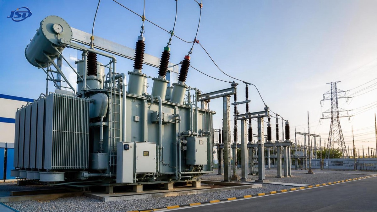
For example, an 110kV Oil-Immersed Transformer may be considered where the project requires voltage transformation for grid connection, plant boosting service, or a renewable-energy step-up arrangement. Available configurations can include two-winding, three-winding, and autotransformer designs, so the technical review should still confirm the winding duty, cooling rating, and network study assumptions for the specific installation. Where FR3 environmentally friendly insulation oil is proposed, include the fluid requirement explicitly and request supporting design information rather than treating it as an interchangeable detail.
Protective features need to match the plant’s maintenance reality
A reliable transformer specification does not end with electrical ratings. It should address the devices that allow operators to detect deterioration before a unit trip or forced outage occurs. Depending on the voltage class and project philosophy, this may include oil and winding temperature indicators, pressure-relief devices, gas-actuated protection, oil-level indication, cooling-system alarms, online dissolved-gas monitoring provisions, bushing monitoring interfaces, and marshalling-box requirements.
The important point is not to request every available device by default. Each device should have a defined purpose, alarm/trip logic, signal destination, testing arrangement, and maintenance access requirement. A monitor that cannot be safely calibrated, sampled, or integrated into the control system creates little practical value.
Physical layout often exposes omissions in otherwise good specifications. Review radiator clearance, fan replacement access, conservator access, cable-box orientation, bushing phase spacing, fire separation, drainage, oil-containment volume, lifting provisions, and transport route limitations. If the transformer must be assembled on site, define which components are shipped separately and what field testing is required after assembly.
Compare bids on declared losses and guaranteed design conditions
Initial purchase price can hide important differences in lifecycle cost. No-load losses remain present whenever the transformer is energized, while load losses increase with current. Their relative importance depends on the expected annual loading profile. A unit that runs continuously at high output may justify a different optimization than one that spends long periods lightly loaded.
Bid evaluation should therefore compare guaranteed no-load and load losses at the stated reference temperature, along with auxiliary consumption for cooling equipment. Confirm that all bidders are using the same voltage, MVA base, tap position, cooling stage, and temperature assumptions. Otherwise, a lower quoted loss figure may not represent a comparable condition.
Efficiency claims should be read in context. Some 110 kV designs are offered with efficiency exceeding 99% and may be designed to meet applicable ecodesign requirements, but the procurement decision should still rely on the guaranteed losses and test conditions stated for the proposed unit. A designed service life of more than 30 years may be relevant to lifecycle planning, yet it does not replace requirements for quality documentation, routine tests, type-test evidence where applicable, factory acceptance testing, and installation controls.
Turn the specification into an approval gate before release
Before the inquiry is issued, hold a focused technical review with the electrical design, protection, civil, operations, grid-interface, and procurement functions. The purpose is to resolve conflicts while changes are still inexpensive. The review should confirm that the transformer rating is tied to the unit operating envelope; ratio and taps are supported by voltage studies; impedance is coordinated with fault-duty and protection studies; and interfaces for cooling, control, grounding, auxiliary supply, and fire protection are unambiguous.
During bid clarification, ask suppliers to identify every deviation in a separate schedule. A transformer can appear compliant because its main nameplate values match the inquiry, while its cooling redundancy, impedance tolerance, tap range, accessory make-up, transport mass, or test scope differs materially. Requiring explicit deviations makes technical comparison more defensible and reduces late-stage redesign.
The final specification should be detailed enough to protect the unit’s operating needs, but not so prescriptive that it blocks a manufacturer from applying proven design practice. The strongest documents describe the required duty, limits, interfaces, tests, and acceptance criteria clearly. That gives the selected manufacturer room to engineer the equipment while keeping responsibility for reliable performance where it belongs.
When a power plant transformer is treated as a system interface rather than a standalone purchase, the selection process becomes far more manageable. The result is not simply a transformer with the right voltage on its nameplate, but one whose rating, thermal behavior, protection, and operating range support dependable unit operation from synchronization through long-term service.

Get a Quote
Regardless of whether you require general advice or specific support, we are happy to help you.
Send Us Your Inquiry Today

Jinshida Electric remains committed to contributing to global energy development through professional manufacturing and superior service.