





Power Station Transformers: Key Protection and Testing Requirements
A transformer outage rarely begins with a dramatic event. More often, the early signs appear during a routine switchyard walkdown, a commissioning review, or a protection relay check: a temperature trend that does not match loading, an unexplained relay target, a secondary wiring discrepancy, or test values that cannot be compared because the previous records are incomplete.
For power station transformers, these small uncertainties can become serious operational risks. A protection scheme may fail to isolate an internal fault quickly enough, or it may trip healthy equipment during an external disturbance. A test result may be accepted without confirming the tap position, temperature, or instrument method used. The practical solution is not simply “more testing.” It is a disciplined link between design review, installation inspection, functional protection testing, baseline electrical measurements, and controlled records.
Start by separating internal faults from system disturbances
The protection philosophy for power station transformers should first distinguish faults inside the transformer protection zone from abnormal conditions originating outside it. Internal winding faults, core faults, bushing failures, lead faults, and insulation breakdown require rapid and selective isolation. External short circuits, overloads, voltage fluctuations, and inrush conditions require protection that supports the transformer without creating unnecessary trips.
This distinction sounds basic, but it is where many coordination problems begin. A relay setting copied from another installation may not match the vector group, CT ratios, tap range, grounding method, or fault level at the actual station. Even a correctly selected relay function can behave incorrectly if polarity, phase association, CT secondary grounding, or trip wiring has not been verified end to end.
Before energization, the responsible technical team should have a current single-line diagram, protection schematic, wiring diagram, CT and VT data, transformer nameplate data, and approved relay settings. These documents should agree with one another. If they do not, field test results alone cannot prove that the overall scheme is dependable.
The protection functions that need deliberate review
Differential protection is normally the primary high-speed protection for major power station transformers. It compares current entering and leaving the protected zone. Under normal conditions and external faults, the relay should remain stable after ratio and phase compensation. For an internal fault, it should operate quickly.
During review, pay close attention to vector group compensation, CT ratios on each side, CT polarity, transformer tap range, and harmonic restraint or blocking logic. Magnetizing inrush can produce a high differential current when a transformer is energized. A differential relay that does not correctly identify inrush may trip immediately after closing. On the other hand, excessive restraint settings can reduce sensitivity to genuine internal faults. Both conditions need to be tested against the approved protection study rather than adjusted by intuition in the field.
Restricted earth fault protection is commonly applied where sensitive detection of earth faults near a grounded winding neutral is needed. Its effectiveness depends heavily on the correct relationship among phase CTs, neutral CTs, and the grounding arrangement. A neutral grounding resistor, solidly grounded neutral, or impedance-grounded system changes the available earth-fault current and therefore changes suitable settings.
Overcurrent and earth-fault protection are generally used as backup protection. They may cover transformer external faults, downstream feeder faults, or failures of primary protection. Time-current coordination matters. A backup relay should clear a persistent fault when required, but it should not outrun the protection closest to the fault without a justified reason.
Thermal protection addresses a different failure path. Winding and insulation life are strongly affected by temperature. Oil-immersed units may use top-oil and winding temperature indicators, while dry-type units commonly use embedded temperature sensors and controller logic. Alarm and trip stages must be clearly assigned. An alarm that is not connected to a monitored point provides little value; a trip stage with no verified breaker interface is equally incomplete.
For oil-filled transformers, sudden pressure, gas-actuated, oil level, and pressure-relief devices may form part of the protection arrangement depending on transformer design. These functions should not be transferred blindly to dry-type equipment. Cast-resin transformers do not contain insulating oil, so oil-level or gas relay functions are not applicable. Their protection focus is more commonly on winding temperature, cooling fan operation where fitted, overtemperature trip circuits, ventilation conditions, and insulation condition.
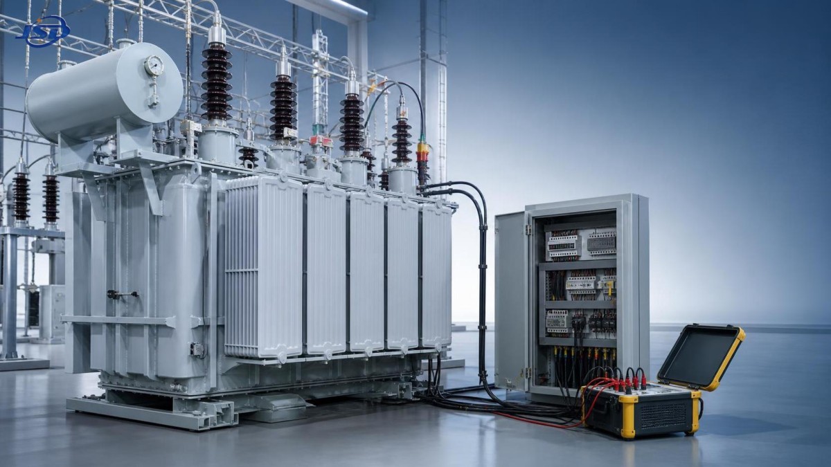
Protection testing should prove the complete trip path
A relay injection test is necessary, but it is not the whole commissioning test. It proves relay measurement and logic under simulated conditions. It does not automatically prove that the correct breaker trips, that the annunciation reaches the intended location, or that lockout logic performs as designed.
A useful commissioning sequence begins with document confirmation and visual inspection. Verify relay model and firmware where applicable, approved setting files, CT and VT connections, trip supply voltage, terminal markings, panel grounding, and cable segregation. Confirm that temporary test links, shorting blocks, and commissioning jumpers are identified and removed or returned to their normal positions before energization.
Secondary injection can then verify pickup values, timing, directional behavior where used, harmonic restraint behavior, alarm contacts, output contacts, and logic equations. For differential protection, the test plan should include balanced through-current conditions, simulated internal-fault conditions, and tests that demonstrate stability for appropriate external-fault scenarios. Test records should state the injected quantity, expected result, actual result, relay setting reference, test instrument identification, and any deviation.
Primary injection or other end-to-end verification may be appropriate when practical and safe. This is particularly valuable when there is uncertainty around CT polarity, phase identification, meter circuits, or complete trip wiring. Where primary injection is not feasible, a carefully controlled secondary end-to-end test should still verify each protective element through to the correct lockout and circuit-breaker interface.
Trip circuit supervision deserves special attention. A healthy relay output does not guarantee a healthy tripping circuit. Check DC supply availability, trip coil continuity, auxiliary contact feedback, lockout relay operation, breaker close-blocking behavior after lockout, and alarm indication for loss of trip-circuit integrity. Any bypass used during testing should have a documented restoration step and independent confirmation before handover.
Electrical tests establish the transformer’s operating baseline
Protection testing answers whether the transformer will be isolated correctly. Electrical testing answers whether the transformer and its connections are in acceptable condition before service. The exact test scope depends on transformer type, voltage class, project specification, manufacturer instructions, applicable standards, and the condition of the unit after transport and installation.
For power station transformers, common acceptance and commissioning measurements include insulation resistance and polarization index where appropriate, winding resistance, transformer turns ratio, vector group or phase displacement confirmation, excitation current, magnetic balance where specified, capacitance and dissipation factor testing for insulation systems and bushings where applicable, and tests on associated surge arresters, cables, and grounding connections.
Winding resistance testing is especially useful after transport, tap changer work, lead reconnection, or suspected contact issues. Measurements should be taken with a stable test current and allowed to settle. Comparing phases without correcting for temperature can lead to false concern, especially where conductor temperature differs from previous records. For units with tap changers, results should be recorded by relevant tap position, and the operation of the tap changer should be evaluated using the procedure specified for that equipment.
Turns-ratio testing helps identify winding connection errors, incorrect tap positions, shorted turns, or mismatched phase connections. The expected ratio must be based on the actual nameplate voltage and selected tap, not merely the nominal system voltage. Vector group confirmation is equally important because a phase displacement error can affect parallel operation and differential protection stability.
Insulation resistance readings should never be judged from a single number alone. Test voltage, ambient temperature, humidity, insulation temperature, test duration, previous operating history, and manufacturer guidance all influence interpretation. A dry transformer exposed to damp site conditions may require drying or corrective action before energization, but the decision should be based on the complete condition assessment rather than one isolated reading.
Standards provide a framework, not a substitute for project-specific engineering
The IEC 60076 series is a major reference family for power transformers. Different parts address general requirements, temperature rise, insulation levels and dielectric tests, short-circuit withstand capability, loading guidance, and dry-type transformer requirements. IEC 60076-11 is particularly relevant when reviewing dry-type transformers. National standards, grid requirements, contract specifications, and local electrical safety rules may add further requirements.
The key practical point is to identify which documents are contractually and technically applicable before testing starts. A test listed in one standard may be a routine factory test, a type test, a special test, or a site test depending on the equipment and specification. Factory test certificates are valuable, but they do not replace site verification after shipping, storage, assembly, cable termination, protection wiring, and final installation.
Acceptance criteria should be agreed in advance. “Within tolerance” is not enough unless the tolerance source is identified. Use the manufacturer’s documented values, approved drawings, applicable standards, and project test procedures. Where a result differs from expectations, first confirm the test setup, connection points, test temperature, tap position, and instrument condition. Repeating a measurement without controlling these variables can create more confusion rather than clarity.
A dry-type installation needs different attention points
In indoor substations, industrial plants, hospitals, data centers, mining facilities, and renewable-energy installations, dry-type transformers are often selected where fire performance and the avoidance of oil leakage are important considerations. Their protection and maintenance approach should reflect their construction and environment.
For example, a 33kV Cast Resin Dry-Type Distribution Transformer can be configured for distribution duties with a 33 kV input and 0.4 kV output, subject to the selected design and project requirements. Its cast-resin construction calls for close attention to temperature sensing, fan-control logic, ventilation clearance, dust accumulation, connection torque, and signs of surface tracking or cracking. Its stated F1-class fire performance and embedded temperature protection features do not remove the need to verify that alarm, fan-start, and trip signals work correctly after installation.
For cast-resin units, inspect coils and insulation surfaces under suitable lighting before energization. Look for contamination, loose foreign material, mechanical damage, moisture-related concerns, and restrictions to cooling airflow. Verify that cable terminations do not impose excessive mechanical stress on bushings or terminals. If forced-air cooling is used to support higher loading, confirm fan direction, controller setpoints, failed-fan alarms, and the operating limits established by the manufacturer.
Records are part of the protection system
When a fault, alarm, or abnormal temperature occurs months later, the most useful reference is usually the commissioning baseline. Keep one controlled package containing nameplate details, factory certificates, installation inspection records, relay settings, test reports, as-left wiring diagrams, functional trip test evidence, and approved deviations. Avoid leaving critical information only in email threads or on an individual technician’s laptop.
During operation, trend loading, temperature indications, cooling equipment status, alarm events, relay self-supervision alarms, and relevant test values. A change from baseline may be more meaningful than a value considered alone. If a protection operation occurs, preserve relay event records and disturbance data before resetting equipment. This helps distinguish a true electrical event from a wiring, settings, CT, or auxiliary-power issue.
Reliable power station transformers depend on a chain of verified details: appropriate protection functions, correctly engineered settings, sound electrical condition, tested trip circuits, and records that can be used later. When each link is checked against the actual transformer design and installation—not assumed from a generic template—the risk of avoidable outages is much easier to control.

Get a Quote
Regardless of whether you require general advice or specific support, we are happy to help you.
Send Us Your Inquiry Today

Jinshida Electric remains committed to contributing to global energy development through professional manufacturing and superior service.