





Industrial Power Transformers: Matching Capacity to Factory Loads
Industrial Power Transformers: Matching Capacity to Factory Loads
Selecting industrial power transformers is not a matter of choosing the largest kVA rating the budget will allow. An oversized unit can carry unnecessary no-load losses for decades; an undersized unit may run hot, limit production expansion, and turn a routine maintenance event into an unplanned shutdown. The right decision sits somewhere between those two extremes, and it depends on how the factory actually consumes power rather than on the connected-load total shown on an early equipment schedule.
For technical evaluators, the difficult part is usually not calculating current. It is understanding the load profile behind the numbers: which motors start together, how often welders cycle, whether harmonic-producing drives are concentrated on one bus, how much spare capacity is genuinely needed, and whether a future photovoltaic or battery system will change the site’s power flow. Industrial power transformers must be matched to those operating realities before details such as enclosure type, cooling method, and tap arrangement can be properly assessed.
Start with demand, not simply installed equipment
A factory may have 2,000 kW of nameplate equipment while rarely drawing anything close to that amount at one time. Conveyors may be idle between batches. Process heaters may cycle. Standby compressors are still included in the equipment register but do not operate with their duty units. On the other hand, a facility with a modest connected load may experience severe peaks if several large motors restart after a utility interruption or if a production line begins a high-load phase at the same time as HVAC demand rises.
The most useful starting document is a time-based load record from the main incomer, ideally covering representative production periods rather than only a quiet week. Where meter data is unavailable, a load study should separate continuous loads, intermittent loads, motor loads, non-linear loads, emergency loads, and expected additions. Demand diversity must be based on the operating plan, not an arbitrary reduction factor. A paper mill, cold-storage warehouse, metal fabrication shop, and electronics assembly plant can have the same connected kW but require very different transformer decisions.
The basic three-phase relationship remains useful:
Transformer kVA = kW ÷ power factor.
That calculation is only the first pass. It does not capture motor starting current, harmonic heating, ambient temperature, altitude, emergency duty, or the capacity margin required by the site’s operating strategy. A transformer rated for the calculated average load can still be a poor fit if the load has sharp, repeated peaks or low power factor during critical production periods.
Capacity margin should be deliberate
A common shortcut is to add a fixed percentage to present demand. It is simple, but it can hide more than it solves. A site planning a second extrusion line within two years may need a clear expansion allowance. A mature plant with stable production and a separate reserved feeder may not. The key question is whether future load will be permanent, temporary, simultaneous, and electrically close to the existing transformer.
A practical evaluation often distinguishes between normal operating demand and the maximum credible operating condition. The latter may include the largest motor starting sequence, a process restart, or the transfer of load from one transformer to another during maintenance. If two transformers are intended to share load or provide backup for each other, their ratings, vector groups, impedance characteristics, and tap settings need coordinated review. “Same kVA” alone does not make two units suitable for parallel operation.
Capacity should therefore be documented as an engineering decision: present maximum demand, assumed power factor, anticipated growth, allowed loading condition, and any operational contingency. This makes later review much easier than relying on a vague note saying “sized with spare capacity.”
Voltage, impedance, and motor starting are closely connected
Factory transformer selection often becomes problematic when voltage regulation is considered late. A transformer can have adequate thermal capacity but still allow an unacceptable voltage dip at a sensitive bus during direct-on-line motor starts. The result may be contactor dropout, PLC alarms, nuisance trips, or unstable operation of variable-speed drives elsewhere in the plant.
Transformer impedance affects both short-circuit current and voltage drop under transient load. Higher impedance can help limit fault current, which may reduce switchgear duty concerns, but it generally increases voltage drop as load changes. Lower impedance may support better starting performance but can raise available fault current beyond the rating of downstream equipment. There is no universally “best” impedance value. It must be coordinated with the utility source, transformer rating, cable runs, motor starting method, protective devices, and short-circuit withstand ratings.
Tap configuration deserves the same attention. If the utility supply has a known voltage range, the available off-circuit or on-load tap arrangement should be reviewed against the required secondary voltage at the actual point of use. A transformer tested at nominal voltage can still leave a distant motor control center under-voltage if long secondary cables and peak loading were overlooked.
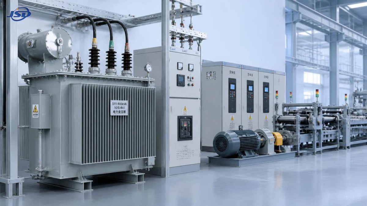
Non-linear loads change the thermal picture
Modern factories increasingly rely on VFD-driven motors, robotic welding, rectifiers, chargers, UPS equipment, and automation systems. These loads can introduce harmonics that increase losses in windings and other transformer components. A conventional load calculation based only on RMS current may therefore be incomplete.
The right response is not automatically to oversize the transformer by a large margin. Evaluators should request the load characteristics from equipment suppliers, identify the expected harmonic sources, and determine whether filtering, line reactors, phase-shifting arrangements, or a transformer designed for the duty is appropriate. Neutral conductor loading and grounding arrangements may also need attention where triplen harmonics are present. Harmonic performance is a system issue: the transformer, switchgear, cables, capacitors, and sensitive controls all need to be considered together.
This is especially relevant when power factor correction capacitors are already installed. Capacitor banks can improve conventional power factor, but they may interact poorly with harmonic conditions if their application is not coordinated. The evaluation should confirm the complete electrical context rather than treating the transformer as an isolated purchase.
Efficiency matters, but lifecycle performance matters more
Losses in industrial power transformers have two different behaviors. No-load loss is present whenever the transformer is energized, including low-production periods. Load loss rises with current and becomes more influential as loading increases. That distinction matters when comparing a transformer that runs continuously at a light load with one that carries a heavily utilized production line over multiple shifts.
A technically sound comparison should ask for loss data at the relevant operating condition, not just an efficiency statement at one point. It should also account for the expected duty cycle and the cost of energy at the project location. In a plant that operates continuously, small differences in losses can accumulate; in a seasonal or intermittently operated facility, reliability, installation constraints, and capital cost may carry more weight.
Environmental conditions are easy to underestimate. High ambient temperature, restricted ventilation, dust, salt-laden air, moisture, altitude, and limited maintenance access can materially affect the practical choice between indoor dry-type equipment, liquid-filled units, or an outdoor packaged arrangement. The question is not merely whether the transformer can be installed at the site; it is whether it can be inspected, protected, and serviced without disrupting the factory’s operating schedule.
When a pad-mounted substation is the better distribution approach
For medium-sized factories, logistics parks, and sites where indoor electrical-room space is limited, a packaged outdoor substation can simplify the interface between the medium-voltage utility supply and low-voltage distribution. It can also reduce the number of separate field-installed components, although civil works, cable routing, access clearances, and utility requirements still need careful coordination.
One option for this type of application is the American-Type Pad-Mounted Substation. The ZGS-750 configuration is specified at 750 kVA, with rated voltage options from 2.4 kV to 34.5 kV. Its stated efficiency is greater than 99%, and its IP54 (NEMA 3R) protection level may be relevant for outdoor locations exposed to dust and moisture. Ring-network, terminal, and photovoltaic step-up variants indicate that the enclosure concept can serve different distribution schemes; the required version should follow the site’s single-line diagram rather than a generic preference.
For sites near sensitive drainage areas or with environmental handling requirements, the specified option of FR3 vegetable oil, described with biodegradability above 95%, may warrant evaluation. That does not remove the need to assess local fire, containment, spill-control, and authority requirements. Similarly, references to IEC 60076, IEEE C57, ANSI/IEEE C57, UL, CSA, CE, and other listed certifications should be checked against the actual project specification, destination market, and required test documentation. Standards alignment is only useful when it is verified for the exact supplied configuration.
Reliability begins before the transformer reaches site
A dependable transformer installation is shaped by specification quality as much as manufacturing quality. Technical schedules should clearly state the primary and secondary voltages, vector group, frequency, kVA rating, impedance requirement, cooling method, tap arrangement, insulation level, enclosure requirement, accessories, monitoring needs, and applicable tests. Ambiguity in any of these areas tends to surface late—often after switchgear, cables, or foundations have already been ordered.
It is also worth reviewing the practical service model. Can the manufacturer provide drawings early enough for civil and cable design? Are factory test records available for review? What spare parts, alarms, gauges, or protection interfaces are needed for the plant’s maintenance practice? Companies such as Jinshida Electric Power Technology Co., Ltd., which combine power equipment R&D, manufacturing, and application support, can contribute most effectively when involved early enough to discuss the whole distribution arrangement rather than only responding to a final kVA request.
The best selection is rarely the transformer with the highest rating or the lowest initial price. It is the unit whose thermal capability, voltage behavior, impedance, efficiency, enclosure, and maintenance demands match the factory’s real operating conditions. Before issuing a purchase order, compare the proposed transformer against a current load study, a future-load plan, and a short-circuit coordination review. Those three checks catch a large share of expensive mistakes while there is still time to correct them.

Get a Quote
Regardless of whether you require general advice or specific support, we are happy to help you.
Send Us Your Inquiry Today

Jinshida Electric remains committed to contributing to global energy development through professional manufacturing and superior service.