





How to Reduce Overheating and Failure Risks in 10kV Transformers
A 10kV transformer rarely fails because of one dramatic event. More often, heat builds quietly: a connection develops resistance, a cooling path becomes restricted, an overloaded period lasts longer than planned, or aging insulation loses its margin. By the time an alarm operates, the damage may already include degraded oil, carbonized contacts, or weakened winding insulation.
The practical goal is not to keep a transformer “cool” at all times. It is to keep temperatures within the limits assumed by its design, identify abnormal temperature rise early, and correct the actual cause before thermal stress becomes an outage. That requires looking at loading, cooling, connections, oil condition, and protection records together rather than treating each reading in isolation.
Where 10kV Transformer Overheating Usually Starts
Heat in a 10kV transformer comes from normal electrical losses, but abnormal heat has a pattern. Copper losses rise rapidly as current increases, while core losses remain present even at light load. A unit may therefore run acceptably during normal production but overheat during shift changes, motor starts, seasonal peaks, or an unexpected load transfer from another feeder.
Overload is the first item to verify, but it should not become the automatic diagnosis. A transformer operating below its expected load can still develop a dangerous hot spot if one terminal is loose, a bushing contact is contaminated, a tap changer has poor contact pressure, or circulation inside the tank is impaired. The overall top-oil temperature may appear only moderately high while a localized connection is already deteriorating.
In practice, the most common causes are:
- Long-duration loading beyond the transformer’s thermal capability or repeated peak loading with insufficient cooling time.
- Blocked radiator fins, failed fans or pumps, poor airflow around the enclosure, and accumulated dust or debris.
- Loose LV or HV terminals, oxidized contact surfaces, damaged cable lugs, and inadequate bolting torque.
- Low oil level, oil leakage, moisture ingress, or degraded oil that no longer transfers heat effectively.
- Unbalanced phase loading, especially where large single-phase loads have been added gradually.
- Insulation deterioration, winding faults, tap changer defects, or abnormal magnetic flux caused by voltage conditions.
The key point is simple: temperature is a symptom. Reducing the reading without identifying the source only delays the next failure.
Start With a Baseline, Not a Single Temperature Reading
A temperature value has little meaning without context. Record ambient temperature, load current on all phases, top-oil temperature, winding temperature where available, cooling equipment status, and the time of day. A 10kV transformer operating at a given oil temperature on a cool morning may deserve more attention than the same temperature during a hot afternoon at a higher load.
Trend data is more useful than a one-time inspection. Compare the same load level over time. If the oil temperature or winding temperature gradually rises while ambient conditions and load are broadly similar, investigate cooling performance, contact resistance, oil condition, and internal losses. A sudden step change deserves faster action because it may indicate a failed fan bank, blocked oil path, new load imbalance, or a high-resistance connection.
A useful working rule is to investigate differences between phases as seriously as high absolute temperatures. One phase carrying substantially more current or showing a warmer cable termination can point directly to the fault area. Do not assume the transformer itself is defective before checking downstream circuits and load allocation.
Control the Load Before It Controls the Transformer
Load review should include more than the transformer nameplate kVA. Check actual hourly demand, power factor, phase balance, motor starting conditions, harmonic-producing equipment, and planned future additions. A transformer that appears correctly sized on a monthly energy report may still face short periods of severe thermal stress that are invisible in averaged data.
Repeated overload should be treated as an operating decision, not a maintenance routine. Temporary overload capability depends on the transformer design, cooling condition, insulation condition, starting temperature, ambient temperature, and duration. It is not a blanket permission to operate above rating whenever production requires it.
For example, some copper-coil oil-immersed designs may permit a short-term load of up to 150% of rated capacity for no more than two hours, provided oil temperature is monitored and kept at or below 95 degrees C. That figure must be confirmed against the specific manufacturer documentation and site conditions. It is not suitable as a standing operating target, and it should not be used for a transformer with existing oil, cooling, or insulation concerns.
When load peaks cannot be avoided, consider practical alternatives: transfer non-critical loads, stagger large motor starts, improve power factor where appropriate, rebalance single-phase circuits, or install additional capacity. Reducing load by a modest amount during the hottest period can produce a much larger improvement in thermal margin than expected.
Airflow and Oil Cooling Need Physical Inspection
Many overheating calls are resolved outside the tank. Outdoor units can accumulate dust, leaves, plastic film, construction debris, or insect nests around radiators and ventilation paths. Indoor transformer rooms may have blocked louvers, failed extraction fans, closed doors, or new equipment placed too close to the transformer.
Walk the installation, not just the control panel. Check that radiator surfaces are accessible and clean, cooling fans rotate in the intended direction, pump indications match actual operation, and warm air can leave the space. For an oil-immersed installation, maintaining sufficient clearance from walls matters; a layout with at least 1.5 metres of space from the wall can help preserve airflow and inspection access where the equipment design and local installation requirements allow.
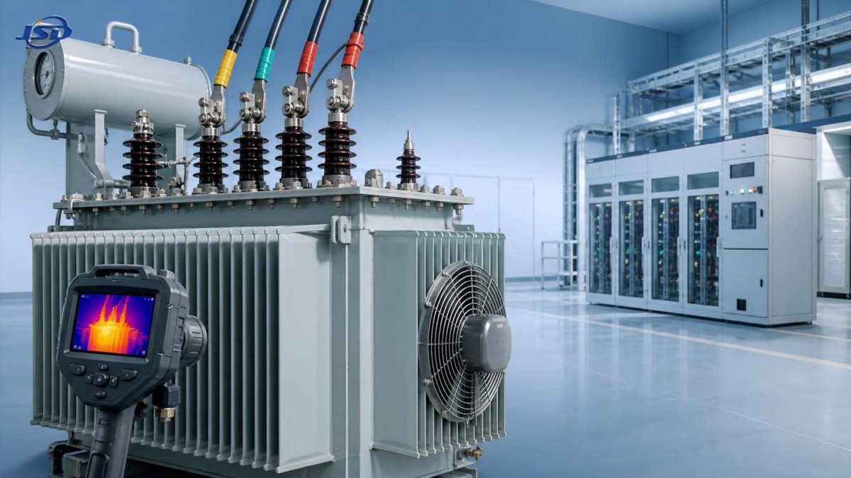
Infrared thermography is especially valuable after the transformer has stabilized under meaningful load. Scan HV and LV bushings, cable terminations, neutral points, grounding connections, radiator headers, tap changer compartments, and cooling fan terminals. A hot connection often appears before it creates an alarm. Thermography is a screening tool, though, not proof by itself: reflected heat, emissivity errors, and differing surface finishes can mislead the operator. Confirm suspicious locations with safe follow-up checks and electrical measurements.
Loose Connections Are Small Defects With Large Consequences
A loose connection creates resistance; resistance creates heat; heat accelerates oxidation and further increases resistance. This feedback loop can damage terminals, cable insulation, bushings, and switchgear surprisingly quickly.
During planned isolation, inspect contact surfaces for discoloration, pitting, melted insulation, hardened grease, corrosion, or signs that a lug has moved. Follow the approved torque values for the actual terminal and hardware. “Tight by feel” is not a reliable standard. Over-tightening can also damage threads, distort contact surfaces, or stress bushing terminals.
Pay particular attention after major work: cable replacement, shutdown maintenance, a fault event, installation of new loads, or transport and relocation. These are the moments when a previously stable transformer can acquire a connection issue.
Oil and Insulation Tell You What Is Happening Inside
For an oil-filled 10kV transformer, the oil is both coolant and diagnostic medium. Visible leakage, a falling oil level, a damaged gasket, or moisture entering through breathers and seals should never be treated as a cosmetic issue. Less oil can reduce cooling performance; moisture and oxidation reduce dielectric strength and accelerate insulation aging.
Routine oil testing should be based on site criticality, equipment history, and the applicable maintenance program. Common assessments may include dielectric breakdown voltage, moisture, acidity, interfacial tension, and dissolved gas analysis. The results need interpretation in context. A single poor value may call for confirmation or investigation; a worsening trend is often more informative than an isolated test result.
Dissolved gas analysis can provide an early warning of overheating, partial discharge, arcing, or other internal activity, but it does not identify every fault with certainty. The correct response is usually to compare historical results, review loading and temperature events, inspect related equipment, and consult the transformer manufacturer or a qualified diagnostic specialist when gas patterns are concerning.
Do not attempt to solve every temperature problem with oil filtration or replacement. If the root cause is a loose LV connection, a failed cooling fan, or excessive harmonics, fresh oil will not remove the source of heat.
Protection Settings Must Match the Real Operating Condition
Overtemperature alarms, winding temperature indicators, pressure devices, oil level alarms, Buchholz relays where fitted, and overload protection are valuable only when they are functional and correctly coordinated. A common weak point is an alarm that has become accepted as “normal” during hot weather. That practice removes the warning margin that protects the transformer when a second problem appears.
Review event records after every trip, alarm, or unusual temperature rise. Note the load level, ambient conditions, switching sequence, cooling stage operation, and protection response. A relay reset without a documented cause turns a useful warning into lost diagnostic evidence.
Protection coordination also needs to reflect changes on the low-voltage side. New variable-speed drives, rectifiers, welding loads, capacitor banks, or large motors can alter current waveform, peak demand, and fault behavior. If the load profile has changed, the transformer assessment and protection review should change with it.
When Repair Is Sensible and When Replacement Is Safer
Cleaning radiators, restoring ventilation, replacing failed fans, correcting load imbalance, repairing leaks, and retorquing connections are often effective when the transformer has no indication of significant internal damage. The decision becomes more serious when overheating has been repeated, insulation test results decline, dissolved gas trends worsen, or the unit is consistently too small for the present load.
Replacement should be evaluated as a reliability decision, particularly for industrial plants, renewable-energy grid connections, public facilities, data-heavy operations, and healthcare sites where an unplanned outage has a high operational cost. The replacement specification should address actual load growth, voltage ratio, cooling conditions, environmental exposure, efficiency requirements, protection interfaces, and maintenance access.
For projects requiring conversion from medium voltage to 400 V-class distribution, the 15kV/0.4kV Oil-Immersed Power Distribution Transformer is an example of a product category that should be assessed against the site’s true duty cycle rather than selected by capacity alone. Options such as FR3 vegetable oil may be relevant where fire safety or environmental considerations affect the specification. The final selection should still be verified against the applicable standards, grid requirements, and installation conditions.
Jinshida Electric Power Technology Co., Ltd. supports power transmission and distribution applications through product development, manufacturing, and quality-focused service. In a maintenance context, the useful contribution is not simply supplying equipment; it is ensuring that the transformer specification, site environment, operating profile, and inspection plan are considered together before a replacement is commissioned.
A Practical Response When Temperature Starts Rising
When a temperature alarm occurs, avoid making abrupt changes without understanding the operating state. First confirm the reading and compare it with load and ambient conditions. Then inspect cooling equipment, room ventilation, oil level, visible leakage, and terminal hot spots using approved safe procedures. Check phase currents and look for a newly added or abnormal downstream load.
If temperature continues to rise, load reduction is usually the safest immediate measure while the cause is investigated. Escalate quickly where there is smoke, oil leakage near hot parts, abnormal sound, strong odor, pressure device operation, repeated alarms, or evidence of arcing. Those signs can indicate a developing internal or connection-related fault that should not be managed through continued operation.
Reliable operation comes from disciplined follow-through: document the event, correct the confirmed cause, verify temperatures after the repair, and update the maintenance history. A 10kV transformer that runs within a stable thermal pattern is far easier to maintain than one that is repeatedly pushed to the edge of its limits.
Frequently Asked Questions
Can a 10kV transformer run hot without being faulty?
Yes. High ambient temperature and legitimate peak loading can raise temperatures. The concern is a temperature rise that is excessive for the load and conditions, increasing over time, or accompanied by phase imbalance, cooling faults, alarms, or abnormal oil test results.
Is cleaning the radiator enough to solve overheating?
It is enough only when restricted heat dissipation is the real cause. Cleaning will not correct overloaded operation, loose terminals, internal winding defects, poor oil condition, or a failed cooling control circuit.
How often should terminal connections be checked?
Use the approved site maintenance schedule, then increase attention after faults, new-load installation, major shutdown work, relocation, or repeated thermal alarms. Thermographic scans under load can help prioritize which connections need closer inspection.
Should an overheating transformer be kept in service until the next outage window?
That depends on the cause, temperature trend, protection status, and site criticality. Continued operation is not appropriate when temperatures are rising uncontrollably, safety devices operate, arcing is suspected, or internal fault indicators are present. Reduce load and follow the site emergency procedure.

Get a Quote
Regardless of whether you require general advice or specific support, we are happy to help you.
Send Us Your Inquiry Today

Jinshida Electric remains committed to contributing to global energy development through professional manufacturing and superior service.