





11kV vs 10kV Transformers: Which Voltage Rating Fits Your Project?
11kV vs 10kV Transformers: Which Voltage Rating Fits Your Project?
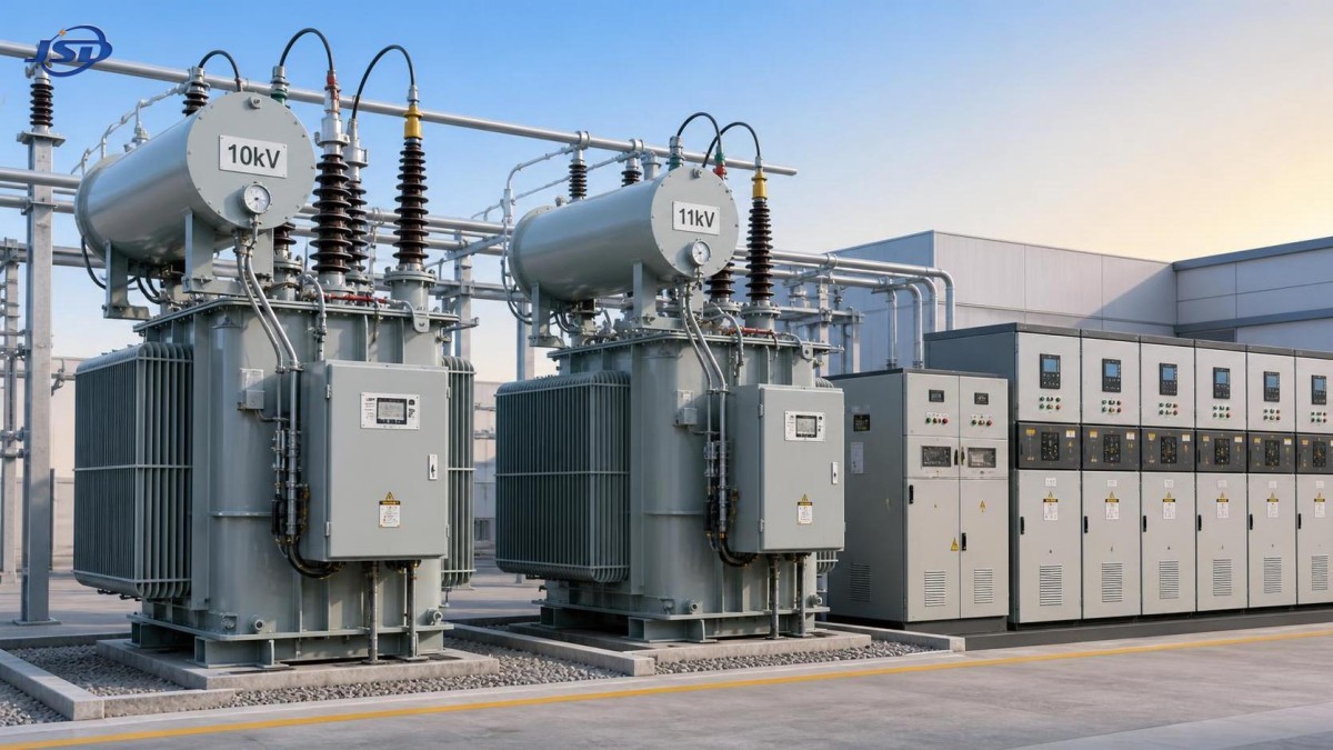
Choosing between an 11kV transformer and a 10kV unit requires more than comparing nameplate voltage. Technical evaluators must confirm system compatibility before reviewing price or delivery.
The correct choice is normally dictated by the upstream distribution network. A transformer should match the actual system voltage, grounding arrangement, insulation requirements, and utility operating tolerances.
For most projects, 10kV equipment suits networks standardized around 10kV. An 11kV transformer is appropriate where the grid nominal voltage, switchgear, cables, and protection systems support 11kV.
Attempting to use one rating as an interchangeable substitute can introduce insulation coordination issues, incorrect tap selection, protection complications, and future expansion constraints.
What Technical Evaluators Are Actually Trying to Determine
Searchers comparing an 11kV transformer with a 10kV model usually need a defensible specification decision, not a general explanation of transformer operating principles.
They want to know whether the selected voltage rating will operate safely on the local grid, meet applicable standards, and avoid unnecessary capital expenditure.
Technical teams also need confidence that transformer losses, impedance, vector group, short-circuit withstand capability, and low-voltage output match downstream equipment requirements.
The decision becomes more important in industrial plants, renewable energy stations, infrastructure facilities, and utility distribution projects with long expected operating lives.
Start With the Utility or Internal Network Nominal Voltage
The first selection rule is straightforward: specify the transformer high-voltage rating according to the nominal voltage of the supplying network.
A 10kV network should generally receive a transformer designed for 10kV service. Likewise, an 11kV network should normally use an 11kV transformer.
Nominal voltage is not simply an administrative label. It establishes the expected operating range for equipment insulation, switching devices, cable systems, surge arresters, and protection settings.
Before releasing a purchase specification, obtain the utility connection agreement, single-line diagram, supply voltage tolerance, fault-level information, and grounding method.
For private industrial networks, confirm whether the incoming feeder is genuinely 10kV or 11kV. Legacy documentation can differ from actual utility operating practice.
Projects with multiple substations should also determine whether each feeder uses the same voltage class. Mixed-voltage sites require clear interface boundaries and disciplined labeling.
Why 10kV and 11kV Are Not Automatically Interchangeable
Although the numerical difference appears small, transformer insulation design is based on voltage class, temporary overvoltage exposure, impulse withstand requirements, and standard test levels.
An 11kV transformer may tolerate a 10kV supply electrically, provided its taps and complete system design are appropriate. That does not automatically make it optimal.
Using a higher-rated unit on a lower-voltage network can reduce available secondary voltage if the off-circuit or on-load tap position is not selected correctly.
Conversely, applying a 10kV transformer to an 11kV supply may overstress high-voltage insulation, increase magnetizing current, and compromise long-term reliability.
The complete primary system matters. Transformer bushings, cable terminations, surge arresters, ring main units, disconnectors, and metering transformers must share compatible ratings.
Therefore, voltage selection should be treated as a system coordination exercise rather than a standalone equipment comparison.
Check the Actual Operating Voltage Range, Not Only the Nameplate
Distribution networks do not operate at one perfectly fixed voltage. Load changes, source regulation, switching activity, and feeder length create normal voltage variation.
Evaluators should request the expected minimum, normal, and maximum primary voltage at the transformer terminals, rather than relying only on a nominal value.
Transformer taps are designed to accommodate expected voltage deviations. However, the tap range and tap step arrangement must be suitable for the project’s operating conditions.
For example, an 11kV transformer serving an 11kV grid may require tapping positions that maintain the specified low-voltage bus voltage during typical supply variation.
Low-voltage performance matters because motors, variable-frequency drives, rectifiers, heating equipment, and sensitive controls can react poorly to sustained voltage deviation.
Where supply conditions are unstable, assess whether off-circuit taps are sufficient or whether an on-load tap changer is justified by the application.
Compare Insulation Coordination and Surge Protection Requirements
Insulation coordination is one of the strongest reasons to avoid casual substitution between voltage ratings. It protects equipment against lightning and switching overvoltages.
Relevant parameters include power-frequency withstand voltage, lightning impulse withstand level, neutral insulation level, bushing creepage distance, and local pollution severity.
Outdoor substations in coastal, industrial, desert, or heavily polluted areas often require more careful insulation and creepage design than sheltered indoor installations.
An 11kV transformer should be evaluated with the associated surge arrester protective level, cable insulation rating, and upstream switching surge characteristics.
Surge arresters must be selected according to system voltage and grounding conditions. An incorrectly coordinated arrester can leave the transformer inadequately protected.
Ask suppliers for insulation test data, bushing details, applicable IEC or ANSI standards, and confirmation that the proposed arrangement matches the site environment.
Capacity Does Not Determine Voltage Rating, but It Changes the Evaluation
Transformer kVA rating and primary voltage rating solve different problems. Capacity defines load-serving capability, while voltage rating defines compatibility with the supply network.
Still, larger transformers require a broader review because their inrush current, fault contribution, impedance selection, cooling system, and transport requirements affect the project.
Calculate demand using diversified load data, expansion forecasts, motor starting conditions, harmonic-producing loads, and the required redundancy philosophy.
Oversizing purely for future growth can increase no-load losses and capital cost. Undersizing can cause excessive temperature rise, voltage drop, and reduced equipment life.
For critical loads, consider two-transformer arrangements, bus sectionalizing, emergency load transfer, and the consequences of a single transformer outage.
Voltage selection remains fixed by the grid, while capacity should be optimized using realistic operating profiles and documented future demand assumptions.
Impedance Selection Can Affect Project Performance More Than the Voltage Difference
Transformer impedance determines how much voltage drops under load and how much short-circuit current the transformer can supply to downstream faults.
A lower impedance can support motor starting and reduce voltage dip, but it also increases available fault current and may require higher-rated switchgear.
Higher impedance can limit fault duty, yet excessive impedance may impair large-motor acceleration or cause unacceptable voltage variation during process load changes.
Technical evaluators should model the transformer together with incoming source impedance, cable lengths, motor starting profiles, generators, and low-voltage protection devices.
Do not select impedance from a generic catalog value without checking coordination studies. The correct percentage depends on rating, application, and network architecture.
This review is equally important for 10kV and 11kV transformers, particularly in industrial facilities with high fault-level exposure.
Assess Secondary Voltage Requirements From the Load Side Backward
The selected transformer must provide a low-voltage output compatible with local utilization equipment, distribution boards, motors, converters, and building electrical standards.
Common secondary voltages may include 400V, 415V, 420V, 440V, or 480V, depending on geography, equipment origin, and industrial process requirements.
Specify the required voltage at the load or main low-voltage bus, then account for transformer regulation, cable voltage drop, and normal supply variation.
A suitable primary voltage rating cannot compensate for a poorly chosen secondary voltage. Incorrect output voltage can create operational issues across an entire facility.
Where imported machinery is involved, verify motor nameplates, control transformers, drive input ranges, and frequency requirements before finalizing the transformer ratio.
For installations needing 13.8kV input and flexible low-voltage outputs, evaluate the 13.8kV Distribution Transformer alongside the project’s complete electrical interface requirements.
Frequency, Vector Group, and Neutral Arrangement Must Be Defined Early
Frequency is a fundamental design input. A transformer intended for 50Hz should not be assumed suitable for 60Hz operation without manufacturer confirmation.
Operating a transformer at lower frequency than designed can increase core flux density and potentially cause overheating, saturation, higher losses, and insulation stress.
Vector group selection affects phase displacement, parallel operation, harmonic behavior, and the availability of a neutral point for low-voltage distribution.
Dyn11 remains common for many distribution applications because it provides a low-voltage neutral and helps manage certain third-harmonic current effects.
However, the correct vector group depends on the network. Parallel transformers must have compatible voltage ratios, vector groups, impedance values, and tap positions.
Specify neutral grounding requirements clearly, especially where earth-fault protection, generator interconnection, sensitive electronic loads, or process continuity are involved.
Losses and Lifecycle Cost Should Influence the Final Selection
Purchase price is visible at procurement stage, but transformer losses continue throughout the unit’s operating life and can materially affect total project cost.
No-load loss occurs whenever the transformer is energized. Load loss rises with current and becomes particularly important in heavily loaded or continuously operating facilities.
Compare guaranteed loss values at the same reference temperature, rating, impedance, and test standard. Lower losses should be evaluated against energy tariffs and loading profiles.
Efficiency assessment should include expected annual load factor, operating hours, electricity cost, cooling energy where relevant, and anticipated service lifetime.
High-quality grain-oriented silicon steel, well-designed windings, and controlled manufacturing processes can reduce losses, noise, and heat generation.
For technically demanding projects, request guaranteed losses with defined tolerances and establish acceptance testing requirements in the procurement specification.
Environmental Conditions Can Change the Required Design
Ambient temperature, altitude, humidity, dust, corrosion, seismic exposure, fire risk, and installation space can influence transformer construction and rating decisions.
High-altitude locations reduce cooling effectiveness and external insulation performance. They may require derating, larger clearances, or specially selected insulation components.
Hot climates can increase winding temperatures, while enclosed transformer rooms may require ventilation studies to prevent heat accumulation and reduced service life.
Oil-immersed transformers require attention to fire separation, oil containment, drainage, access, and local regulations. Dry-type units may suit specific indoor applications.
Outdoor units need durable enclosures, suitable paint systems, corrosion protection, and appropriate ingress protection for terminal boxes and control cabinets.
These environmental factors do not decide whether 10kV or 11kV is correct, but they determine whether the selected unit remains dependable in service.
Use Standards as a Procurement Baseline, Not a Substitute for Engineering
Standards define essential test methods, tolerances, design expectations, and quality controls. They help purchasers compare technically similar transformer proposals fairly.
IEC 60076 is widely used for power transformer requirements, while IEEE and ANSI standards may apply in projects following North American practices.
Project specifications should identify applicable standards, required routine tests, type test evidence, insulation levels, temperature rise limits, and acceptable loss values.
Ask whether test reports relate to the offered design, rather than a distant product family. Critical data should be traceable to the actual equipment configuration.
Factory acceptance testing should verify ratio, vector group, winding resistance, insulation resistance, impedance, no-load loss, load loss, and dielectric performance.
For higher-risk projects, witness testing or independent inspection can provide useful confirmation before shipping and reduce commissioning-stage surprises.
A Practical Decision Process for 11kV Transformer Selection
Begin with the point of connection. Confirm the utility’s nominal voltage, maximum voltage, grounding arrangement, short-circuit level, and applicable connection requirements.
Next, establish the required secondary voltage, frequency, total demand, future growth allowance, power factor, harmonic profile, and critical load expectations.
Then perform load-flow, short-circuit, protection coordination, and motor-starting studies. These calculations turn basic transformer parameters into a project-specific recommendation.
Define insulation levels, tap range, vector group, impedance, cooling method, enclosure type, environmental conditions, and monitoring requirements in the technical specification.
Compare suppliers using guaranteed technical data, test capability, quality documentation, delivery schedule, lifecycle losses, warranty terms, and local service capacity.
Finally, review the transformer as part of the complete substation. Switchgear, cables, arresters, meters, earthing, and protection relays must all be compatible.
Common Specification Errors to Avoid
A frequent mistake is ordering an 11kV transformer because it appears more robust, without confirming that its ratio and taps suit a 10kV supply.
Another error is selecting capacity only from connected load totals. This ignores diversity, duty cycle, motor starting, harmonic heating, and future load management.
Some specifications omit impedance, vector group, or insulation level. These omissions invite supplier assumptions that may conflict with protection and operating requirements.
Evaluators should also avoid comparing loss figures without confirming the same test basis. Similar-looking numbers may represent different temperatures or rating conditions.
Choosing equipment solely on initial cost often overlooks energy losses, outage exposure, maintenance access, spare-part support, and the cost of late design changes.
A clear technical schedule reduces these risks and enables meaningful evaluation across multiple compliant transformer offers.
Final Recommendation
The right choice between 10kV and 11kV transformers begins with the actual supply network, not a preference for one voltage class over another.
Select a 10kV unit for a verified 10kV system and an 11kV transformer for a verified 11kV system, then optimize taps, impedance, capacity, and insulation.
For technical evaluators, the strongest procurement decision is supported by network studies, documented operating conditions, lifecycle cost analysis, and a complete compliance specification.
When voltage rating, secondary requirements, protection coordination, and environmental design are aligned, the transformer becomes a reliable long-term asset rather than a project risk.

Get a Quote
Regardless of whether you require general advice or specific support, we are happy to help you.
Send Us Your Inquiry Today

Jinshida Electric remains committed to contributing to global energy development through professional manufacturing and superior service.