





How Copper Windings Improve Heat Dissipation Under Continuous High-Load Operation
Copper windings improve thermal performance under continuous high load primarily by reducing winding resistance. Lower resistance produces less load loss at the same current, so less heat has to leave the coil, insulation, oil, tank, and surrounding air. This matters because winding temperature is not determined by electrical loss alone. It is the result of heat generation, the paths available for heat transfer, the cooling medium, ambient temperature, and the duration of the load.
For a transformer carrying a sustained heavy load, the relevant loss is commonly expressed as I2R. Current rises with load, while the resulting resistive loss rises with the square of current. A modest increase in current can therefore create a disproportionate rise in heat. Copper does not eliminate this relationship, but its relatively low electrical resistivity reduces the starting value of R. With appropriate conductor cross-section and winding design, the coil produces less heat for a given duty point than a higher-resistance alternative.
Heat begins inside the conductor
Transformer windings are densely arranged conductors separated by insulation and assembled around the core. Heat generated in an inner turn must travel through conductor material, insulation layers, oil ducts or air channels, and the external cooling system before it reaches the environment. The hottest location is often inside the winding rather than on the tank surface. A tank that feels only moderately warm does not prove that the winding hot spot is within an acceptable range.
Copper has high thermal conductivity as well as low electrical resistance. Heat generated in a copper conductor spreads along and across the conductor more readily, reducing severe local temperature differences within a well-designed coil. This supports a more uniform thermal field, especially where current density is high or where several layers of winding are closely packed. Uniformity matters because insulation aging is governed by the hottest local area, not by the average oil temperature.
The benefit is conditional on conductor geometry. A copper winding with insufficient cross-section still has high current density and can run hot. Conversely, a conductor with ample cross-section but poor cooling paths can retain heat in inner layers. Copper is therefore part of a thermal system, not a substitute for adequate ducting, insulation design, oil circulation, radiator capacity, or installation clearance.
Resistance, temperature, and the feedback effect
Copper resistance increases as temperature rises. Under a prolonged load, this produces a feedback loop: current causes conductor loss, conductor loss raises winding temperature, and the warmer copper has greater resistance. The increase is predictable, but it becomes important when thermal margins are already narrow. A design with lower initial resistance has more room before this feedback adds significant extra loss.
At stable load, heat generation and heat removal eventually approach balance. The final temperature is not reached immediately. Oil-immersed units have thermal inertia, so temperatures can continue rising after the electrical load has stopped increasing. Short-duration readings taken soon after a load change may therefore underestimate the eventual winding and oil temperature. Continuous high-load operation should be assessed against the time-temperature response, rather than against a single instantaneous measurement.
Winding resistance tests are useful for comparing phases and detecting abnormal connections, but they cannot alone verify thermal behavior at service load. Test values are typically corrected to a reference temperature. A low corrected resistance indicates efficient conductor performance, yet the operating result also depends on actual load current, cooling condition, winding arrangement, and the temperature of the insulating liquid or surrounding air.
Conductor size is often more important than the material label
The phrase high efficiency copper winding transformer is meaningful only when it reflects the complete winding design. Copper permits a compact winding for a given resistance target, but compactness can reduce cooling-channel space if it is pushed too far. The best arrangement balances electrical resistance, mechanical strength, dielectric clearances, oil circulation, and heat transfer from the inner coil sections.
Current density is a practical indicator because it links conductor cross-section with the current being carried. Excessive current density concentrates I2R loss into a smaller conductor volume. During a long heavy-load period, the inner low-voltage winding can become a thermal constraint because it carries high current and may be located where heat removal is less direct. High-voltage windings carry lower current, but their smaller conductors, insulation build, and position in the winding assembly still require attention.
A larger copper cross-section reduces resistance, but it also changes coil dimensions and mechanical forces. Designers must preserve oil ducts and insulation distances rather than simply filling available space with more conductor. Reduced channel area can restrict natural oil circulation; the reduced electrical loss may then be partly offset by poorer heat transfer. The relevant comparison is the expected hot-spot temperature at the specified load profile, not conductor weight alone.
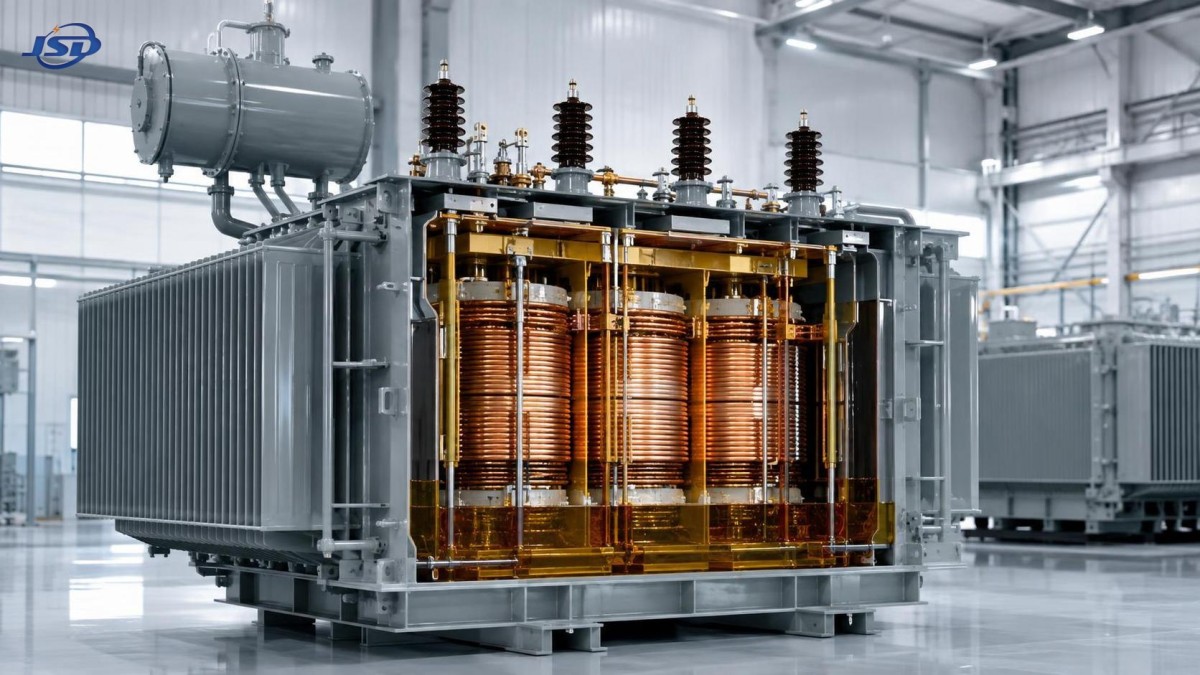
How heat leaves an oil-immersed copper winding
In an oil-immersed transformer, copper transfers heat through its surface insulation into the insulating liquid. Heated oil becomes less dense and rises, while cooler oil moves downward to replace it. This natural circulation carries heat to the tank walls and radiators. Cooling performance declines when oil flow is obstructed, the oil level is unsuitable, radiators are fouled, or the surrounding space prevents effective convection.
Winding ducts are deliberate passages that guide oil through regions where heat is produced. Their layout is especially significant under continuous heavy load. Radial ducts shorten the heat path from conductor layers to moving oil. Axial ducts allow vertical flow through the winding structure. A winding with acceptable average temperature but poorly distributed circulation can still develop a hot area in a restricted section.
Oil condition also affects the thermal path. Moisture, oxidation products, and suspended contaminants can degrade dielectric condition and interfere with heat transfer surfaces. These issues do not always cause an immediate temperature alarm, yet they reduce margin during a later high-load event. A rise in oil temperature caused by degraded cooling should not be assumed to be a winding-material problem. The cause may be external radiator fouling, limited airflow, unsuitable oil condition, a failed cooling component, or a sustained load above the thermal design point.
Separating similar temperature symptoms
Several conditions can produce a high top-oil temperature, but they require different responses. Copper windings reduce load loss, while core loss is influenced mainly by core design and excitation conditions. If temperature remains elevated during low-load periods, or rises after a voltage condition changes without a comparable current increase, the issue may not be winding loss. A persistent temperature rise at normal current can also indicate poor cooling rather than inadequate conductor sizing.
Infrared inspection is valuable for accessible terminals, bushings, cable joints, radiator headers, and tank surfaces, but it cannot directly see the inner winding hot spot. An apparently cool external surface can coexist with a high internal temperature when the heat path is restricted. Temperature indicators, load history, dissolved-gas analysis where applicable, and electrical test records provide a more complete basis for judging internal thermal condition.
High-load operation needs a load profile, not a nameplate-only view
Nameplate capacity is a defined thermal rating under stated conditions. It does not describe every operating environment. A transformer exposed to high ambient temperature, direct solar heating, enclosed installation, blocked radiator airflow, harmonic-rich load, or frequent peaks may reach a high internal temperature at a load that appears acceptable when considered only as a percentage of rated kVA.
Harmonic current requires particular care. Higher-frequency components increase AC effects in conductors, including skin and proximity effects, and can add stray losses in windings and structural parts. Copper remains beneficial because of its low resistivity, but a simple RMS current comparison may understate heating where waveform distortion is substantial. The load spectrum and transformer design must be considered together.
For short-term overload, the allowable duration is inseparable from existing oil temperature and cooling conditions. A copper-coil 15 kV unit designed for short-duration loading may allow operation at 150% of rated capacity for no more than two hours when oil temperature is monitored and kept at or below 95 degrees C. That statement does not establish a universal overload rule: initial temperature, ambient conditions, load waveform, and the cooling state determine whether the same duty is thermally acceptable.
In a 15 kV to low-voltage distribution application, the 15kV/0.4kV Oil-Immersed Power Distribution Transformer illustrates the connection between copper winding design and the cooling environment. Its 30-5000 kVA range covers very different thermal duties. Selection should therefore use the actual voltage, expected load duration, harmonic content, site ambient conditions, and available installation clearance rather than capacity alone.
Installation details can erase thermal margin
Natural cooling depends on air moving around the tank and radiators. Locating an oil-immersed unit too close to a wall traps heated air and lowers the temperature difference that drives heat rejection. A clearance of at least 1.5 meters from a wall is specified for the referenced product configuration; site-specific drawings and safety requirements remain controlling. Louvers, enclosures, cable trenches, and roof structures should be reviewed as a single airflow path rather than as separate construction details.
Dust, leaves, fibers, and industrial deposits on radiator fins reduce effective surface exposure. The result is often gradual: the transformer runs normally in mild weather, then reaches a temperature limit during seasonal heat or sustained process load. Cleaning should avoid damaging coatings, fin walls, gauges, wiring, or energized components. Any inspection or cleaning work must follow the approved isolation and site safety procedure.
Terminal connections deserve equal attention. A loose or oxidized joint generates localized resistance heating outside the winding. This can be mistaken for a transformer internal problem, especially when load rises at the same time. Discoloration, abnormal infrared readings, or an uneven phase temperature near a bushing should lead to a connection inspection before conclusions are drawn about the coil.
What to monitor during sustained loading
Temperature trend is more informative than a single peak. Record load current, top-oil temperature, ambient temperature, cooling equipment status, and the time spent near the highest load. Where a winding temperature indicator is available, compare its trend with top-oil temperature. A growing difference between the two under similar load conditions can signal a change in internal heat transfer or loading behavior.
- Phase current balance: an overloaded phase does not share its heat evenly with the other phases, even when total transformer loading appears reasonable.
- Rate of temperature rise: a faster rise than prior comparable load events points toward changed cooling, higher ambient temperature, altered load quality, or an emerging connection issue.
- Oil level and visible leakage: reduced liquid level can impair heat transfer and must be investigated with the unit in its approved safe state.
- Cooling path condition: radiator surfaces, airflow openings, and any fitted fans or pumps need to be available before a long high-load interval begins.
Copper windings deliver their strongest thermal advantage when low-resistance conductors are combined with correctly maintained cooling and a load profile that matches the transformer’s thermal capability. The material reduces the heat produced at the source; the rest of the design and installation must still remove that heat continuously enough to protect insulation and preserve stable service.

Get a Quote
Regardless of whether you require general advice or specific support, we are happy to help you.
Send Us Your Inquiry Today

Jinshida Electric remains committed to contributing to global energy development through professional manufacturing and superior service.