





Choosing a Three-Phase Copper-Winding Transformer for Motor Loads and Harmonics
A three-phase copper-winding transformer can be a sound choice for motor-heavy installations, but copper alone does not make the transformer suitable. For a project supplying pumps, compressors, conveyors, crushers, HVAC plant, or process drives, the selection must account for how motors start, how often they cycle, and whether variable-speed drives are adding harmonic current to the system.
The first decision is therefore not “copper or aluminium,” nor simply “how many kVA.” It is whether the transformer has been specified around the electrical behaviour of the connected loads. A transformer that appears adequately rated under steady-state conditions can still suffer excessive voltage dip during motor starts, elevated winding temperature from harmonics, or an unusable margin for future process expansion.
For projects where motor availability matters, copper windings are often justified when the full design also addresses impedance, thermal performance, connection arrangement, protection coordination, and operating profile. They are less compelling when the transformer is oversized only to compensate for an unclear load study.
Start with the motor duty, not the transformer nameplate
Motor loads rarely behave like a flat, predictable kW demand. A directly started induction motor can draw several times its running current for a short period. If multiple large motors start near the same time, the transformer secondary voltage can dip enough to prevent another motor from accelerating, cause contactors to drop out, or disturb sensitive controls on the same low-voltage bus.
A project manager should ask for the motor schedule before approving transformer capacity. At a minimum, it should identify each motor’s rated power, starting method, starting current, starting duration, duty cycle, and the sequence in which major motors may start. The answer changes materially between a plant with one large pump on a soft starter and a system with several direct-on-line motors restarting after a process interruption.
Running load establishes the baseline. Starting demand determines whether that baseline is operationally credible.
- Direct-on-line starting creates the highest inrush exposure and often drives the voltage-dip assessment.
- Star-delta, autotransformer, or soft-starter starting can reduce line current, although starting torque and process requirements still need review.
- Variable-frequency drives usually reduce motor starting stress but introduce harmonic current and can alter the transformer thermal duty.
- Frequent starts, reversals, plugging, or high-inertia acceleration increase the importance of thermal cycling and voltage stability.
A common mistake is to add all installed motor ratings, apply a generic diversity factor, and select the next available transformer size. That method can miss the worst operating state: for example, a loaded conveyor starting while process pumps and ventilation fans are already running. Conversely, it can result in unnecessary oversizing where an interlocked start sequence prevents coincident starts. The load study should describe real operating modes, including restart conditions after a supply disturbance.
Copper winding construction supports this duty well because copper provides high electrical conductivity and can help manage winding losses within a compact design. Yet the project specification should still require the manufacturer to state the temperature-rise basis, load loss, impedance tolerance, and permissible loading assumptions. “Copper-wound” is a material description, not a complete motor-duty guarantee.
Impedance determines whether motors see enough voltage to start
Transformer impedance is one of the most consequential values in a motor application. Higher impedance limits fault current, which can help switchgear duty and protection coordination, but it also increases voltage drop under high starting current. Lower impedance improves voltage support at motor terminals, while increasing available fault current downstream.
There is no universally correct impedance value. The appropriate choice depends on transformer capacity, feeder length and conductor size, utility source strength, motor starting current, existing switchgear ratings, and the acceptable voltage dip for controls and other connected loads. A transformer may perform well at its secondary terminals but still leave inadequate voltage at a distant motor because cable impedance adds to the drop.
For this reason, the engineering review should assess the whole source-to-motor path rather than treating the transformer as an isolated component. A useful study normally includes the upstream network contribution, transformer impedance, low-voltage bus arrangement, major feeder impedance, and the voltage profile during the identified starting scenarios.
Do not solve every voltage-dip concern by specifying the lowest possible transformer impedance. That can transfer the problem to the low-voltage switchboard, circuit breakers, busbars, and protective-device settings. The better outcome is a coordinated design in which the transformer, starting method, and distribution equipment are selected together.
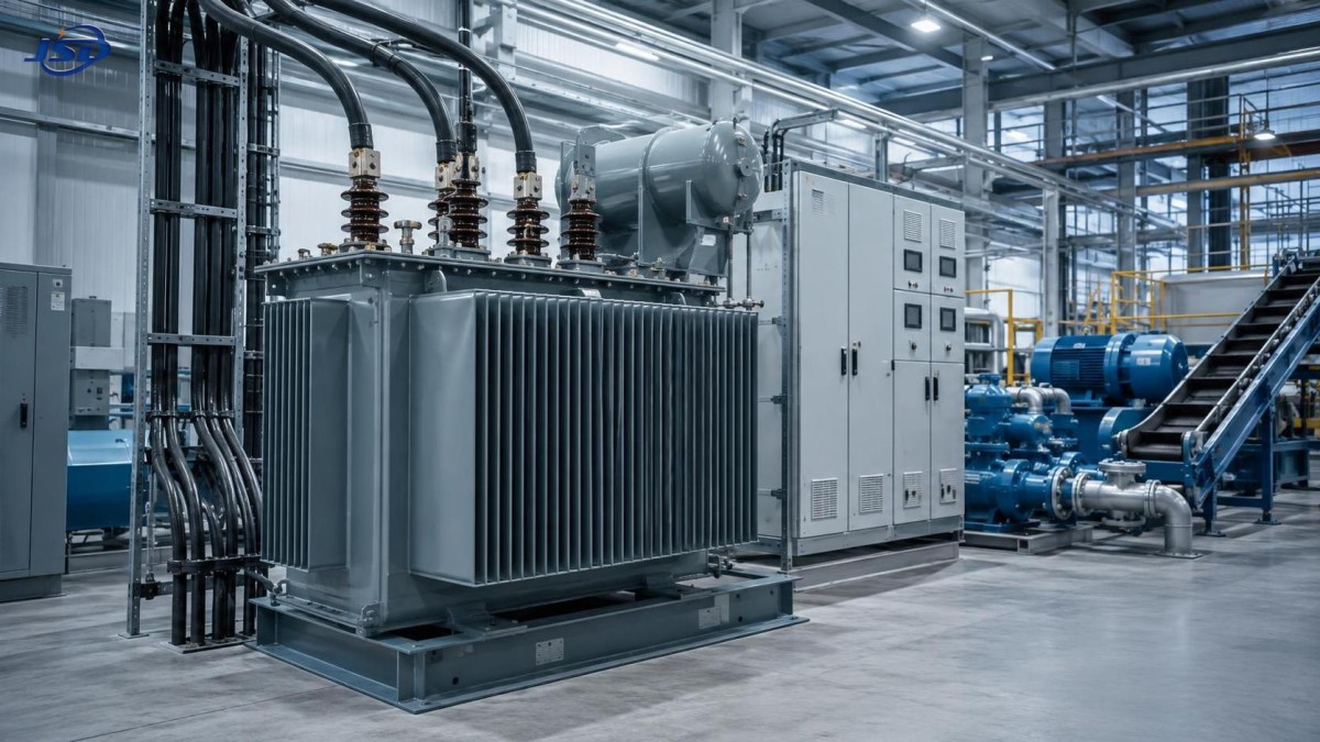
For a 33 kV-to-400 V distribution application feeding an industrial low-voltage network, the 33kV Oil-Immersed Power Distribution Transformer provides an example of the parameters that should be examined together: capacity range, off-circuit tap options, short-circuit impedance, winding material, losses, and overload limits. A stated 6.5% impedance, for instance, is useful only after it is checked against the motor-starting calculation and downstream fault-level constraints.
Harmonics change the thermal calculation
Where motors are controlled by variable-frequency drives, the transformer should not be selected from fundamental-frequency load current alone. Drive front ends can draw non-sinusoidal current. Those harmonics increase losses in windings and structural parts, and they can raise transformer temperature beyond what a conventional sinusoidal load calculation suggests.
The practical question is not whether the site has “some drives.” It is how much of the transformer load is nonlinear, what drive topology is used, whether harmonic mitigation is included, and whether the drive loading changes by operating mode. A small number of lightly loaded drives may have little effect on the overall transformer. A distribution bus serving many active rectifier loads, six-pulse drives, UPS systems, or other power-electronic equipment requires a more deliberate assessment.
The procurement package should ask for the anticipated harmonic spectrum or, where that is not yet available, a realistic estimate of the nonlinear load share and drive configuration. This allows the manufacturer and electrical designer to evaluate additional eddy-current and stray losses, derating needs, neutral loading where applicable, and any requirement for an enhanced harmonic-duty design.
Copper windings can offer a thermal and loss-performance advantage, but they do not eliminate harmonic heating. A copper-wound transformer with an ordinary thermal design can still be overloaded by a harmonic-rich load. The specification should make the harmonic duty explicit rather than assuming the conductor material absorbs the risk.
Connection vector also deserves attention. Delta windings can provide a circulating path for certain triplen harmonic components and can help prevent their transfer into the upstream system. That characteristic can be useful, but it is not a substitute for harmonic analysis, filters, line reactors, active front ends, or properly selected drive equipment. The required vector group should follow grounding, protection, parallel-operation, and harmonic-management requirements for the particular network.
Capacity margin should be based on heat and operating scenarios
Project teams often ask for a simple spare-capacity percentage. A fixed percentage is convenient for a budget estimate, but it is weak as a final selection rule. Capacity margin should reflect expected load growth, ambient conditions, motor starting duty, harmonic content, redundancy philosophy, and the consequences of an outage.
Continuous loading close to the nameplate limit may be acceptable under defined conditions, but it leaves little room for process changes or abnormal duty. On the other hand, an oversized transformer incurs higher no-load losses over its entire energized life. For installations that run continuously at low load, this can matter more than a short interval of peak load.
The distinction between no-load and load losses is important in project economics. No-load losses occur whenever the transformer is energized. Load losses rise with current and become especially relevant on heavily loaded, motor-intensive systems. A technically sound comparison therefore uses the expected annual load profile rather than looking only at purchase price or a single efficiency claim.
Short-term overload capability should also be treated carefully. Some copper-coil oil-immersed designs may allow temporary loading above rated capacity under defined temperature limits. This can be useful for managed peak events or contingency operation, but it is not a routine operating margin. Oil temperature, winding hot-spot conditions, ambient temperature, loading duration, and prior thermal history all affect what is acceptable. Building a normal duty cycle around emergency overload capability reduces insulation-life margin and obscures the need for adequate installed capacity.
Questions that should be answered before issuing the specification
- What is the maximum coincident running load, expressed in kVA as well as kW?
- Which motor produces the most demanding start, and what other loads are online at that time?
- What voltage dip can the motor, control system, and process safely tolerate?
- What percentage of load is supplied through VFDs, rectifiers, UPS equipment, or other nonlinear devices?
- What transformer impedance range is acceptable after fault-level and motor-starting studies?
- Will the transformer operate continuously, cycle heavily, or remain lightly loaded for long periods?
- Is future capacity intended for known equipment, or is it an undefined contingency allowance?
Oil insulation and site conditions still affect the choice
For outdoor substations and larger distribution duties, oil-immersed transformers are frequently selected for their cooling capability and established service approach. The insulating liquid selection, containment arrangement, fire-safety requirements, access for inspection, and environmental conditions should be resolved early. A vegetable-oil option such as FR3 may be relevant where the project places particular emphasis on fire point or environmental considerations, but its use should be evaluated with the complete transformer and site design rather than treated as a universal upgrade.
Physical installation details can become operational constraints. Clearance for cooling, cable termination access, radiators, lifting, inspection, and future replacement needs to be included in the substation layout. A unit placed too close to walls or enclosed without adequate ventilation may lose the thermal margin assumed during selection. Where a minimum wall clearance is stated by the manufacturer, the civil layout should preserve it rather than trying to recover space during construction.
Off-circuit taps are suitable where supply voltage adjustments are infrequent and can be made during planned isolation. They do not correct fast voltage changes caused by motor starts or rapidly changing loads. If the project relies on frequent voltage regulation to maintain process conditions, the voltage-control strategy should be reconsidered rather than expecting an NLTC transformer to perform an on-load regulation function.
What to require from suppliers
A comparable bid requires more than a kVA rating and a statement that the windings are copper. Request guaranteed values for no-load loss, load loss, impedance, voltage ratio and tap range, insulation class, temperature rise, cooling arrangement, and applicable test standards. Where motor duty or harmonics are material, state the required operating assumptions in the inquiry and ask suppliers to identify any derating, design adjustment, or limitation.
Short-circuit mechanical strength also merits attention in industrial systems with substantial available fault current. Winding movement caused by fault forces can create damage that is not obvious at commissioning but weakens long-term reliability. The transformer design, fault duty, protection clearing time, and switchgear coordination should all align with the calculated system fault level.
Factory routine tests verify important baseline characteristics, but they should be read alongside the design data. A project team should confirm that the tested and guaranteed configuration matches the ordered voltage, vector group, impedance, tap arrangement, cooling class, and winding material. Substitutions made to meet delivery dates can alter losses, impedance, dimensions, or thermal performance in ways that matter for a motor-driven installation.
Selecting a three phase copper winding transformer for motor loads is therefore a coordinated electrical decision. Copper can support efficient, robust winding design, particularly where loading is demanding. The final specification earns its value when it proves that the transformer will maintain usable voltage during starts, remain within thermal limits under harmonic duty, coordinate with the fault level, and retain enough capacity for the operating plan the project will actually run.

Get a Quote
Regardless of whether you require general advice or specific support, we are happy to help you.
Send Us Your Inquiry Today

Jinshida Electric remains committed to contributing to global energy development through professional manufacturing and superior service.