





Furnace Transformer Selection: Key Ratings for Steel, Smelting, and Arc Furnace Loads
Furnace transformer selection starts with the load curve, not with nameplate capacity alone. Steel, ferroalloy, and non-ferrous melting processes impose severe current swings, frequent short-time overloads, and repeated thermal cycling. A unit that looks adequate on steady-state kVA may still run hot, lose voltage stability at the electrodes, or age prematurely if the duty profile is not matched to the transformer design. The practical question is whether the transformer can support the full operating envelope of the furnace, including ignition, refining, tapping interruptions, and the irregular transitions between them.
For arc furnace service, the first rating to scrutinize is the relationship between rated power, operating cycle, and permissible overload. The furnace transformer is usually asked to carry low-voltage, very high-current loads with abrupt fluctuation. In selection work, it is useful to separate continuous thermal capability from short-duration process demand. A transformer may tolerate temporary loading above nominal values, but only within a defined cooling condition and with winding hot-spot limits in mind. If the process schedule includes long melting stages with repeated peak current, the thermal reserve should be evaluated against the actual heat run rather than against isolated peaks.
Capacity Must Be Read Together with Furnace Duty
Rated capacity is often treated as the headline value, yet in furnace applications it is only meaningful when paired with duty method. Resistance furnaces, submerged arc furnaces, ladle furnaces, and electric arc furnaces stress the transformer in different ways. A submerged arc furnace may present comparatively stable but extremely heavy current demand, while an arc furnace can create rapid fluctuations, harmonics, and short-circuit-like conditions during scrap cave-ins or unstable arc periods. If the process includes frequent starts and stops, the transformer may cool unevenly, which changes how conservative the thermal design should be.
Attention should also be given to whether the quoted rating is based on natural cooling, forced oil circulation, forced air assistance, or a staged cooling arrangement. A design that only reaches its full stated output after auxiliary cooling is fully engaged should be reviewed carefully where ambient dust, cooling-water quality, or fan maintenance is uncertain. In dirty metallurgical environments, cooling surfaces can foul, filters can load up, and effective heat rejection may drift below the assumed design condition.
Impedance Is a Process Variable, Not Just a Protection Value
Short-circuit impedance has direct influence on furnace behavior. Higher impedance can limit fault current and reduce mechanical stress during disturbances, but it also increases voltage drop under load. Lower impedance improves voltage stiffness at the furnace terminals, though it may expose the system to stronger current surges and tougher electrodynamic forces in the windings. There is no universal best figure; the right range depends on furnace type, upstream network strength, electrode regulation strategy, and how sensitive the melt process is to arc stability.
For electric arc furnaces, impedance should be reviewed together with expected electrode movement and secondary circuit layout. Even when the transformer itself is properly specified, long secondary conductors, reactor additions, or busbar geometry may change the effective circuit behavior enough to alter arc performance. Selection errors often happen when impedance is compared between suppliers without confirming whether the same reference conditions were used, including tap position, temperature basis, and whether auxiliary reactance is inside or outside the transformer scope.
Mechanical strength follows from this discussion. Furnace transformers are exposed to repeated through-fault stress, especially during unstable melt conditions. Winding clamping structure, conductor support, and insulation spacers should be considered as real selection points, not hidden manufacturing details, because electrodynamic fatigue can accumulate long before obvious electrical failure appears.
Voltage Range and Tap Arrangement Decide Process Flexibility
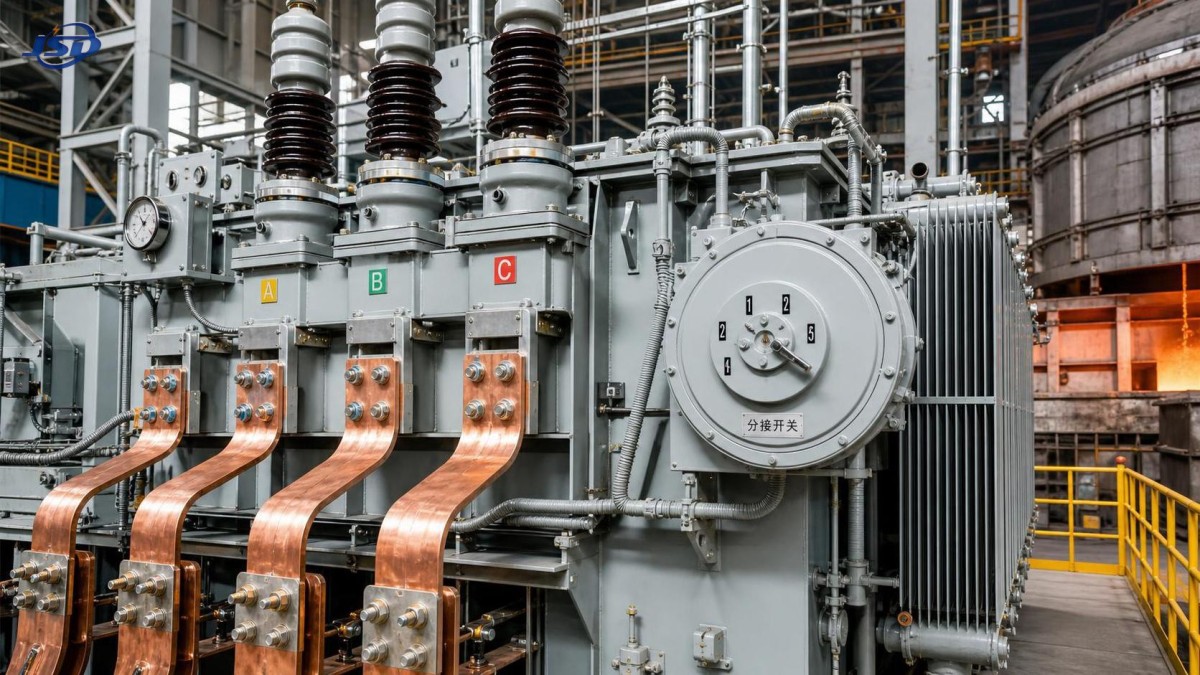
A wide adjustment range on the high-voltage side or a multi-step secondary output is often needed because furnace conditions do not remain fixed through the heat. Scrap composition, burden density, bath condition, and arc length all shift the preferred operating point. The tap changer arrangement therefore deserves close reading. The number of taps matters, but step size matters more than many specifications suggest. If voltage steps are too coarse, control becomes jerky and the furnace may spend too much time between ideal operating points.
Whether the application uses off-circuit tap changing or on-load tap changing should be aligned with process continuity. In applications with frequent power adjustment requirements, an on-load tap changer may be justified, but its maintenance envelope must be realistic for the site. Contact wear, oil cleanliness, switching duty, and inspection access should all be considered. In some installations, a simpler off-circuit arrangement paired with external control measures may prove easier to sustain over time, provided operational interruptions are acceptable.
Voltage regulation assessment should include the complete path from source to furnace. Transformer ratio alone does not define the actual electrode voltage once bus duct losses, contact resistance, reactor drop, and cable heating are included. A technically correct selection often depends on requesting calculated secondary voltage at the furnace terminals under representative current, not merely no-load values at the transformer bushing.
Cooling Design Has to Match the Real Environment
Furnace transformer cooling cannot be evaluated in a clean-room mindset. Steel and smelting sites may involve metallic dust, radiant heat, vibration, and restricted airflow around the equipment bay. A design that performs well in standard test conditions may behave differently when radiators are exposed to scale dust or when cooling air recirculates in an enclosed transformer room. Oil flow path, radiator arrangement, fan redundancy, and temperature monitoring points should therefore be reviewed with the installation layout, not in isolation.
Water-cooled components, if included in the wider furnace circuit, add another layer of selection risk. Water quality, leak detection, isolation strategy, and freeze protection can influence transformer availability even if the core-and-coil assembly itself is robust. Where auxiliary power reliability is uncertain during plant disturbances, it may be reasonable to consider how supporting equipment such as a Silent Canopy Diesel Generator Set fits into the broader continuity plan for cooling auxiliaries and control systems, since a thermal event can develop quickly after forced cooling is lost.
Secondary Current Path Deserves the Same Attention as the Transformer Core
Many furnace transformer problems attributed to the transformer are actually secondary circuit problems. The current path from the low-voltage bushings to the furnace can generate intense local heating if joints are poorly prepared, if flexible connectors are undersized, or if magnetic loop effects were overlooked in busbar routing. During selection, bushing current rating, terminal arrangement, spacing, and mechanical accessibility should be checked against the real bus duct design. Even a well-rated transformer can become awkward to install or service if the terminal geometry forces sharp bends, unequal current sharing, or excessive joint count.
Low-voltage bushings also need mechanical and thermal review. Furnace duty can produce vibration, conductor movement, and radiant heating from nearby equipment. The selected bushing type should suit contamination level and maintenance access. In some heavy-duty layouts, it is worth examining whether phase segregation, shielding, or modified enclosure design is needed to control hot spots and stray losses around the terminals.
Losses, Harmonics, and Stray Heating
Efficiency comparisons should not be reduced to no-load and load loss figures alone. Furnace operation often introduces harmonics, asymmetry, and irregular current waveform that increase stray losses in structural steel parts, tank walls, and lead exits. Those losses may not dominate a standard transformer application, but in a furnace transformer they can become part of the thermal bottleneck. Questions about shielding, magnetic flux control near the tank, and conductor transposition are therefore part of technical evaluation, especially where long campaigns at elevated current are expected.
When upstream network conditions are weak or harmonic-sensitive, the transformer should be reviewed together with any reactor, filter, or compensation arrangement. A furnace transformer chosen purely on its own nameplate can still create operational issues if system interaction is ignored. Voltage flicker, reactive demand, and harmonic distortion are plant-level matters, yet the transformer specification shapes all three.
Insulation System and Dielectric Margins
Dielectric strength in this service is challenged by more than nominal system voltage. Switching surges, repetitive tap operations, and process disturbances can impose complex stress on insulation. Oil-paper insulation quality, drying process, moisture control during manufacturing, and transport handling all affect long-term reliability. If the transformer will travel over rough roads or be stored before installation, transport bracing, impact monitoring, and oil preservation method become relevant selection items rather than logistics footnotes.
On site, the commissioning plan should include checks for insulation condition after transport, verification of cooling auxiliaries, oil testing where applicable, and confirmation that protection settings reflect furnace service rather than a generic power transformer template. A common misjudgment is assuming standard differential and overcurrent settings can be transferred directly; furnace inrush, operating fluctuation, and process-related transients usually require more careful coordination.
Procurement Documents Need Process Details, Not Generic Transformer Language
A weak technical specification often causes comparison errors later. If bidders are only given primary voltage, secondary voltage, and kVA, the returned proposals may differ in impedance basis, cooling assumptions, tap range interpretation, and overload philosophy. A useful inquiry package should describe furnace type, expected power factor behavior if known, operating stages, ambient conditions, altitude if relevant, secondary conductor concept, and any constraints on footprint, noise, or maintenance access. It should also state what has to be included in the thermal and electrical scope, such as bushings, OLTC duty, monitoring devices, and temperature alarm logic.
Inspection points matter as well. Core material grade, conductor material, brazed or bolted joint execution, clamping structure, and oil containment details can affect service life, but they are often buried in vendor drawings unless called out early. For this class of transformer, review of routine test items should be complemented by attention to impedance tolerance, temperature-rise method, and any special test that clarifies behavior under furnace-like conditions.
Installation Constraints Can Change the Preferred Design
Space around the transformer, routing path into the furnace bay, and lifting limitations may eliminate some otherwise acceptable designs. Radiator detachable sections, conservator orientation, cable box access, and bushing removal clearance should be checked before the order is frozen. In retrofit work, existing foundations and busbar elevations can force awkward adaptations. It is usually better to resolve those mechanical interfaces during selection than to compensate later with site modifications that add electrical loss or maintenance difficulty.
Grounding and shielding details also deserve early attention. Stray magnetic fields around high-current secondary runs can induce heating in nearby steelwork, cable trays, or support frames. That issue may remain invisible in a conventional specification review yet become a persistent site problem after energization.
The strongest furnace transformer selections are usually the ones that tie electrical ratings, thermal limits, mechanical design, and installation reality into one consistent picture. When those parts are reviewed together, the specification becomes much harder to misread and much easier to compare in a meaningful way.

Get a Quote
Regardless of whether you require general advice or specific support, we are happy to help you.
Send Us Your Inquiry Today

Jinshida Electric remains committed to contributing to global energy development through professional manufacturing and superior service.