





Rectifier Transformer Basics: Why Phase Shift and Harmonics Matter in DC Systems
When people first look into a rectifier transformer, they often focus on the obvious job: converting AC supply into a form that supports DC processes. That is important, of course, but it is only the surface of the story. In real industrial systems, the difference between a stable, efficient DC installation and a troublesome one often comes down to two less visible issues: phase shift and harmonics.
These are not abstract textbook concerns. They affect transformer heating, rectifier performance, voltage quality, upstream network stress, and even the lifespan of connected equipment. For engineers, procurement teams, and project planners trying to understand how DC systems behave in practice, learning these basics makes it much easier to judge whether a transformer design is suitable for electrolysis, variable speed drives, battery charging infrastructure, traction supply, or other rectified power applications.
A rectifier transformer is therefore not just a standard transformer placed in front of a rectifier. It is usually designed with specific winding arrangements, voltage adaptation, insulation coordination, and thermal considerations so the AC source and the rectifier unit can work together reliably under non-linear load conditions.
What makes a rectifier transformer different from an ordinary power transformer?
At a glance, both devices transfer electrical energy through electromagnetic induction. The key difference lies in the nature of the load. A conventional power or distribution transformer typically feeds relatively balanced linear loads. A rectifier transformer, by contrast, feeds a rectifier bridge that draws current in pulses rather than in a smooth sinusoidal shape.
That single change creates several design consequences. The transformer may need to handle:
- Higher harmonic currents
- Additional heating in windings and structural parts
- Special secondary voltage configurations for rectifier circuits
- Phase-shifted outputs for multi-pulse rectification
- Stricter voltage regulation requirements under fluctuating DC demand
In other words, the transformer must do more than “step voltage up or down.” It must support rectification behavior without becoming the weak point in the system.
Why phase shift matters more than many newcomers expect
Phase shift sounds technical, but the idea is manageable. In rectifier systems, phase shift refers to the intentional angular displacement between different transformer secondary outputs. This is often achieved through different winding connections such as delta, wye, zigzag, or specially arranged secondary windings.
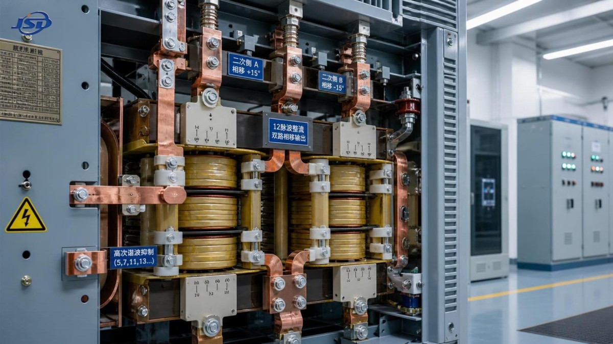
Why introduce phase shift on purpose? Because it helps build multi-pulse rectifier systems, such as 12-pulse, 18-pulse, or 24-pulse arrangements. These systems combine outputs from multiple rectifier bridges that are fed by phase-shifted transformer windings. When designed properly, certain harmonic components from one bridge are offset by those from another. The result is cleaner input current and improved overall power quality.
For someone in the research stage, this is the practical takeaway: phase shift is not a side feature; it is a core harmonic mitigation strategy.
If a DC system uses a simple 6-pulse rectifier, harmonic distortion on the AC side is usually much more pronounced. In many industrial environments, that may increase losses, interfere with nearby equipment, and make compliance with utility or plant power quality expectations more difficult. A 12-pulse arrangement, enabled by transformer phase shift, is often chosen because it offers a meaningful improvement without the complexity of very high pulse systems.
That is why transformer selection cannot be separated from rectifier topology. A buyer comparing solutions only by voltage rating and kVA may miss the real design question: what phase relationship is required to support the desired pulse number and harmonic performance?
Understanding harmonics in plain terms
Harmonics are current or voltage components at frequencies that are multiples of the fundamental power frequency. In a perfect AC system, the waveform is a clean sine wave. In a rectifier-fed system, current is drawn in discontinuous pulses, distorting that wave. Those distortions are what we call harmonics.
Why does this matter so much in a rectifier transformer application?
Because harmonics are not harmless electrical noise. They can lead to:
- Extra heating in transformer windings and core-adjacent metal parts
- Increased losses in cables and busbars
- Reduced power factor at the system level
- Nuisance tripping or stress on switchgear and protective devices
- Voltage distortion that affects other loads on the same network
- Faster aging of insulation if thermal stress is not controlled
In facilities where several non-linear loads operate together, these effects can accumulate quietly. A system may appear acceptable during early operation, then later show overheating, unstable performance, or unexpected maintenance frequency. This is one reason experienced project teams look beyond nominal ratings and pay close attention to load waveform characteristics.
The link between pulse number and harmonic performance
A useful rule of thumb is that higher pulse rectification generally improves harmonic behavior on the AC side. A 6-pulse system is common and economical, but its harmonic signature is relatively strong. A 12-pulse configuration, achieved with phase-shifted transformer secondaries, can significantly reduce dominant lower-order harmonics. Higher pulse arrangements can further improve performance where the network is sensitive or process stability is critical.
Still, more pulses do not automatically mean the best choice in every project. The right decision depends on installation size, grid conditions, process sensitivity, cost constraints, and available space. In some applications, a well-designed 12-pulse system offers a practical balance. In others, additional filtering or more advanced converter technology may be justified.
This is where early technical discussion becomes valuable. Manufacturers with strong application knowledge can help align the transformer design with the real operating environment instead of treating it as an isolated component.
What engineers and buyers should check before selecting a rectifier transformer
Many specification sheets look reassuringly complete, but they do not always reveal whether the transformer is truly matched to the DC system. If you are still at the information-gathering stage, a few questions can quickly clarify the situation.
- What rectifier type will be used? The transformer design depends heavily on whether the system is 6-pulse, 12-pulse, or another configuration.
- What phase shift is required? This determines winding arrangement and harmonic cancellation capability.
- What are the harmonic current expectations? Thermal design should reflect real waveform stress, not only ideal sinusoidal assumptions.
- How stable is the upstream grid? Weak grids may be more vulnerable to distortion and voltage fluctuation.
- What duty cycle will the DC process have? Continuous heavy-duty operation is very different from intermittent service.
- Are there space, cooling, or environmental constraints? Indoor, outdoor, corrosive, high-temperature, or dusty sites all affect design priorities.
These questions are especially relevant in industrial manufacturing, power conversion stations, and energy projects where system downtime carries a real operational cost.
Common misunderstandings that lead to poor system decisions
One common misconception is that harmonic problems can always be solved later with external filters. Filters certainly have their place, but they should not be used as an excuse to ignore transformer-rectifier coordination at the design stage. If phase shift, impedance, and thermal margins are poorly matched from the beginning, downstream corrections may become more complex and expensive.
Another misunderstanding is that a standard distribution transformer can simply replace a rectifier transformer if the voltage ratio appears suitable. In some light-duty situations, that assumption may seem tempting. But rectifier loads impose non-linear stress patterns that an ordinary transformer may not be optimized to withstand over the long term.
It is also easy to underestimate the impact of future expansion. A plant may initially install one rectifier unit, then later add more DC loads on the same network. Harmonic conditions that were once manageable can become problematic after expansion. Thinking ahead during transformer selection can save considerable redesign effort later.
How rectifier transformer design supports long-term reliability
The most dependable designs account for electrical theory and operating reality at the same time. That means attention to conductor sizing, insulation system performance, leakage reactance, mechanical strength under load fluctuations, and cooling behavior under harmonic-rich current conditions.
In broader power distribution architecture, it is also useful to remember that rectifier systems do not stand alone. They connect to substations, feeders, switchgear, and often other transformers serving conventional loads. In many projects, a rectifier installation may coexist with standard equipment such as an 10kV/0.4kV Oil-Immersed Power Distribution Transformer, each serving different roles within the same electrical ecosystem. Understanding where the rectifier transformer fits in that chain helps planners make more balanced decisions about network quality, load segregation, and equipment compatibility.
For companies working across grid construction, industrial manufacturing, new energy, and infrastructure development, this broader view matters. Jinshida Electric Power Technology Co., Ltd. approaches power equipment with that system-level mindset: not simply as isolated products, but as part of safe, energy-efficient, and reliable transmission and distribution solutions. In rectifier applications especially, that perspective is valuable because performance depends on how the transformer interacts with the entire power path.
When should harmonic control become a priority?
The honest answer is: earlier than many teams expect. Harmonic control should become a serious topic when any of the following are true:
- The DC load is large relative to the plant or feeder capacity
- There are sensitive electronic loads nearby
- The utility or project has strict power quality requirements
- Continuous-duty industrial processes depend on stable operation
- Transformer overheating or unexplained losses have been a past issue
Waiting until commissioning problems appear is rarely the most efficient path. By that stage, layout, procurement, and cabling decisions may already limit the available options.
A practical way to think about it
If you are new to the subject, think of a rectifier transformer as a translator between the AC network and the DC process. A good translator does not just pass information along. It reshapes it, aligns it, and reduces misunderstanding between two very different sides. In electrical terms, phase shift helps align multi-pulse rectification for lower distortion, while harmonic-aware design helps the transformer survive and perform under the real current waveforms that DC conversion creates.
That is why phase shift and harmonics matter so much. They influence efficiency, thermal performance, network cleanliness, and equipment life in ways that are easy to overlook at the concept stage but difficult to ignore once the system is energized.
For information seekers comparing options, the smartest next step is not merely asking for a transformer rating. It is asking how the transformer will behave in the actual rectifier system: what pulse configuration it supports, what harmonic conditions it is designed for, and how its construction protects long-term reliability. Those answers reveal far more than a nameplate ever will.

Get a Quote
Regardless of whether you require general advice or specific support, we are happy to help you.
Send Us Your Inquiry Today

Jinshida Electric remains committed to contributing to global energy development through professional manufacturing and superior service.