





Distribution and power transformer differences in utility projects
Distribution and Power Transformer Differences in Utility Projects
Understanding distribution and power transformer differences is essential when a utility project moves from a one-line diagram into actual equipment selection. Both transformer types transfer electrical energy between voltage levels through electromagnetic induction, and both may look broadly similar on a specification list. In practice, however, they sit at different points in the network and are exposed to very different operating pressures. Treating them as interchangeable usually leads to an incomplete technical evaluation.
The practical question is not simply whether a transformer can step voltage up or down. Evaluators need to ask where the unit will operate, what loads it will serve, how faults will be cleared, how much loss is acceptable over its lifetime, and what happens when the surrounding system is expanded. A transformer that is sensible at a transmission substation may be unsuitable at the edge of a distribution feeder, even if the nominal voltage ratio appears workable.
Where Each Transformer Sits in the Electrical Network
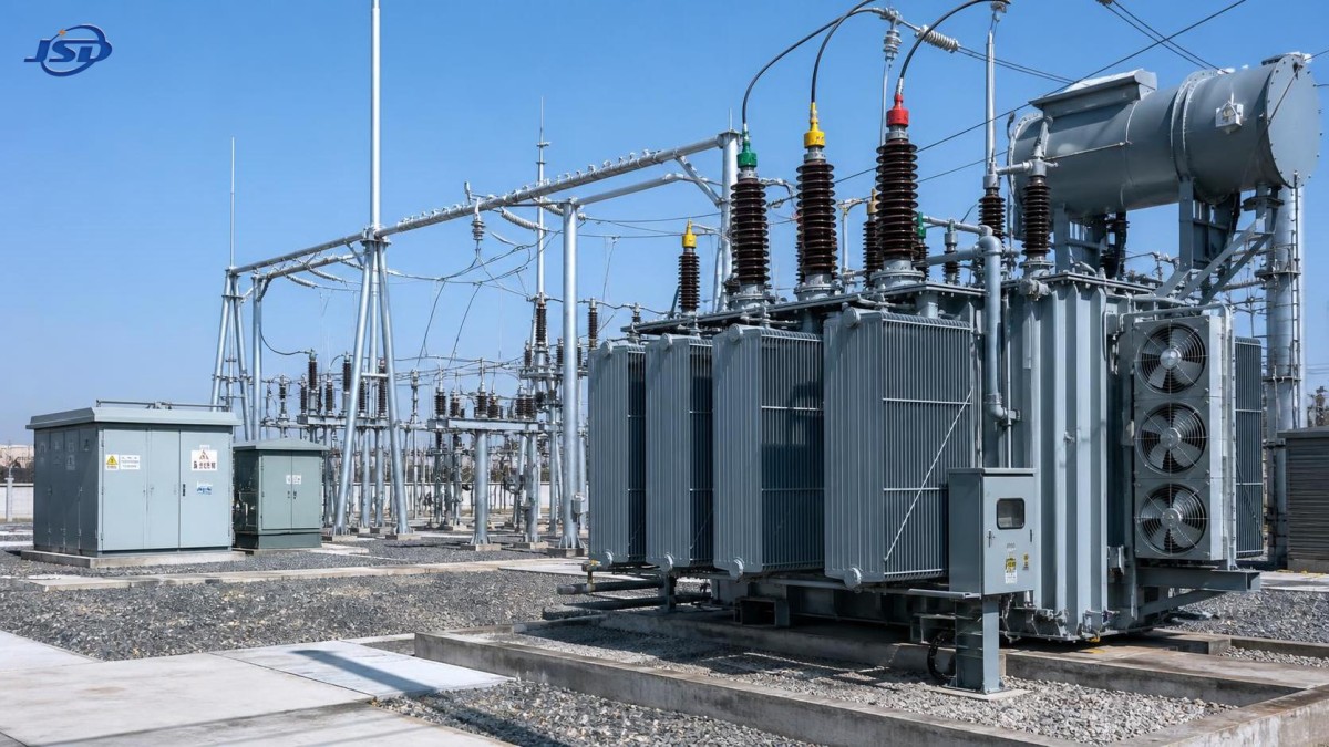
A power transformer is generally associated with bulk power transfer in generation, transmission, and major substation applications. It often connects high-voltage networks, steps voltage up near a generating source, or reduces transmission voltage to a sub-transmission or primary distribution level. These units are commonly selected around system-level concerns: high capacity, short-circuit withstand capability, voltage regulation, network interconnection, and continuous operation under demanding loading conditions.
A distribution transformer operates closer to the end user. Its job is to reduce medium-voltage electricity to a voltage suitable for commercial buildings, residential districts, public facilities, smaller industrial loads, or local equipment. Pole-mounted units, pad-mounted transformers, compact substations, and indoor dry-type transformers are familiar forms. Their place in the network means they are often numerous, geographically dispersed, and exposed to local environmental conditions that a large substation transformer may never encounter.
That location changes the engineering priorities. A utility may install only a limited number of large power transformers at key substations, while deploying many distribution transformers across a service area. For the former, outage consequence and system coordination can dominate the decision. For the latter, no-load loss, installation practicality, public safety, access for maintenance, and consistency across a fleet can have just as much weight.
Capacity Is Only Part of the Difference
It is common to describe power transformers as “large” and distribution transformers as “small.” That is directionally useful but technically incomplete. Ratings overlap in some projects, especially where industrial substations or renewable facilities sit between traditional transmission and local distribution boundaries. The more reliable distinction is the transformer’s duty within the system.
A power transformer may be expected to support substantial energy transfer while maintaining acceptable voltage conditions across connected networks. Its tap changer arrangement, impedance, winding configuration, cooling method, insulation coordination, and protection interfaces can all affect system behavior. An on-load tap changer may be central to maintaining voltage during changing grid conditions. Yet it also introduces maintenance requirements that need to be acknowledged early rather than treated as a procurement detail.
Distribution units are frequently optimized for efficient service over long energized periods. Since many spend much of their lives connected but lightly loaded, core loss can matter considerably in fleet-level energy consumption. Load loss still matters, particularly in dense urban districts, industrial estates, or fast-growing communities, but the right balance depends on the expected load profile. A unit chosen solely for a low purchase price can become an expensive choice if its losses are poorly matched to the actual operating pattern.
This is why nameplate kVA or MVA should not be the starting point and the end point. Evaluators should review projected loading, ambient temperature, altitude where relevant, harmonic content, future connections, and the utility’s permitted overload philosophy. A nominally adequate transformer may have little practical margin if the feeder is expected to absorb electric vehicle charging, new process loads, or distributed generation within a few years.
Voltage Regulation, Impedance, and Fault Performance
The distribution and power transformer comparison becomes more consequential when voltage regulation and fault levels are considered. Transformer impedance influences both voltage drop under load and the available short-circuit current downstream. Neither very low nor very high impedance is automatically preferable. Low impedance can improve voltage regulation but may increase fault duty on switchgear and cables. Higher impedance can help limit fault current but may produce more voltage variation when large loads start or fluctuate.
At a transmission or primary substation, impedance must be coordinated with the wider network study. Parallel transformer operation makes this especially important. Units with significantly mismatched impedance or tap settings may not share load as expected, and circulating current can become a real operating issue. The specification should define the intended parallel arrangement rather than assuming that similar ratings guarantee compatibility.
On a distribution feeder, the concern may be more local but no less practical. A transformer serving motors, welding equipment, crushers, pumps, or a rapidly varying commercial load can experience voltage dips that are not obvious from average demand figures. Harmonic-producing loads add another layer. The transformer itself does not “remove” harmonics; its winding connection, impedance, thermal design, and the system’s harmonic study need to be considered together. When this review is skipped, overheating or poor voltage quality may later be blamed on the transformer even though the underlying issue is the load environment.
Installation Environment Can Change the Transformer Category Decision
The installation setting often narrows the viable choices before the final electrical design is complete. A large oil-immersed power transformer requires attention to transport dimensions, lifting points, oil containment, fire protection arrangements, cooling clearance, monitoring access, and the site’s civil design. A technically excellent unit is still a poor project choice if it cannot be delivered through the available road route or maintained safely once installed.
Distribution transformers face a different set of constraints. A pad-mounted unit in a public area needs an enclosure appropriate to the location and sufficient clearance for cable work. A pole-mounted unit must suit the structural and environmental conditions at the site. Indoor installations may favor dry-type construction where fire-risk management, ventilation, and building access are critical considerations. There is no universal answer between oil-filled and dry-type designs; project requirements, local rules, duty cycle, and maintenance capability decide the trade-off.
Special environments should be treated as a design input, not an afterthought. Mining sites, for example, may include confined spaces, dust, moisture, vibration, and potentially hazardous atmospheres. A conventional utility distribution transformer cannot simply be assumed suitable because the voltage and capacity appear correct. Equipment such as a Mining Flameproof Transformer is evaluated against the specific safety and installation conditions of the mine, along with applicable local requirements and the complete protection scheme.
Losses, Cooling, and the Reality of Service Life
Transformer efficiency is often discussed as if one number settles the matter. It does not. Core loss occurs whenever the transformer is energized, while winding loss rises with load current. A lightly loaded transformer installed in large numbers may justify particular attention to no-load loss. A heavily loaded substation transformer may require closer review of load loss, thermal performance, cooling stages, and emergency loading assumptions.
Cooling design is more than a nameplate notation. It affects allowable loading, acoustic performance, maintenance routines, auxiliary power needs, and behavior during high ambient temperatures. For a critical power transformer, the availability of cooling equipment and the logic for alarms or automatic control can influence operational risk. For a compact distribution installation, a simpler arrangement may be preferable if the duty does not justify additional complexity.
Technical evaluators should also distinguish between a transformer designed to operate reliably and one designed to be maintainable in the actual project environment. Oil sampling points that are difficult to reach, inaccessible radiators, nonstandard terminal arrangements, or incomplete documentation can make routine service unnecessarily difficult. Those shortcomings tend to appear years after commissioning, when the original procurement decision is hard to revisit.
A More Useful Evaluation Path
For utility projects, it is usually better to begin with the system duty and work toward the product configuration. Define the source and receiving voltage, grounding method, load profile, anticipated expansion, fault level, parallel operation requirements, environmental conditions, protection philosophy, and installation limits. Only then should the team compare transformer designs, materials, cooling options, taps, accessories, and supplier documentation.
A few questions expose many specification gaps:
- Will the transformer operate continuously near its planned rating, or remain lightly loaded for long periods?
- Is voltage regulation expected locally, or controlled upstream by another transformer or regulator?
- Can the downstream switchgear withstand the fault current associated with the selected impedance?
- Will future renewable generation, motor loads, or nonlinear loads alter the original assumptions?
- Can the unit be transported, installed, tested, monitored, and serviced within the physical limitations of the site?
These questions apply whether the project involves a grid substation, a manufacturing facility, an infrastructure corridor, or a distributed energy connection. They also explain why a capable transformer manufacturer needs more than production capacity. Technical interpretation, manufacturing process control, quality management, and responsive service all affect whether the delivered equipment matches the network it will enter.
Jinshida Electric Power Technology Co., Ltd. approaches power transmission and distribution equipment with that broader project view: reliable electrical performance has to be supported by practical manufacturing, rigorous quality control, and an understanding of the installation duty. For utility and industrial teams, the useful outcome is not merely selecting a power transformer or a distribution transformer. It is selecting a configuration that remains safe, efficient, serviceable, and compatible with the system as it changes.
The clearest rule is simple: use a power transformer when the project requires bulk transfer and grid-level control; use a distribution transformer when electricity must be delivered efficiently and safely to localized loads. Then test that rule against real network studies, site conditions, and future demand. That final check is where many technically sound projects avoid expensive corrections later.

Get a Quote
Regardless of whether you require general advice or specific support, we are happy to help you.
Send Us Your Inquiry Today

Jinshida Electric remains committed to contributing to global energy development through professional manufacturing and superior service.