





Distribution Transformers for Rural Grids: Capacity and Reliability Considerations
Distribution Transformers for Rural Grids: Capacity and Reliability Considerations
Reliable rural electrification depends on more than placing transformers at convenient points along a feeder. Rural networks often combine long line lengths, dispersed loads, uneven load growth, exposure to storms, and limited maintenance access. A transformer that appears adequate on a nameplate can still become the weak point of the system if voltage drop, seasonal demand, protection coordination, or environmental conditions were underestimated during design.
For project managers and engineering leaders, the central question is not simply “What kVA rating is needed?” It is how to deploy distribution transformers that maintain acceptable voltage, tolerate foreseeable overload and fault conditions, and remain practical to inspect and replace over a long operating life. The answer usually comes from looking at the transformer, feeder, load profile, and site as one connected system.
Why Rural Transformer Selection Is Less Straightforward
In compact urban networks, transformers may serve relatively predictable loads over short low-voltage circuits. Rural distribution is different. One unit may supply homes, irrigation pumps, small businesses, telecom equipment, schools, agricultural processing, or future connections that are not yet active. Peak demand can move sharply between seasons and even between times of day. In agricultural areas, motor starting currents can create short-duration voltage dips that residents experience as poor supply quality even where the transformer is not continuously overloaded.
Long medium-voltage and low-voltage lines add another constraint: voltage regulation. Increasing transformer capacity does not automatically solve low end-of-line voltage. If the low-voltage network is too long or conductor size is insufficient, a larger unit may reduce loading but leave customers with the same voltage-drop problem. In some projects, adding smaller, strategically located transformers and shortening the low-voltage run is a more resilient approach than installing one large central transformer.
Accessibility also changes the economics. A unit installed near a paved road can be inspected, repaired, or exchanged much more easily than one located across difficult terrain. The selected arrangement should reflect realistic maintenance capability, not only initial construction cost.
Capacity Starts with the Load Profile, Not a Rule of Thumb
A sound capacity decision begins with an estimate of diversified demand rather than connected load alone. The connected load of a rural settlement can look large on paper, while simultaneous demand remains modest. Conversely, a feeder serving water pumping or crop-processing equipment may develop a concentrated peak that household diversity assumptions fail to capture. Engineers should separate residential, commercial, agricultural, public-service, and productive loads before selecting a rating.
The practical design review should examine present demand, expected connections, load coincidence, motor loads, power factor, and the likely timing of expansion. It should also distinguish a predictable growth plan from a speculative one. Oversizing every transformer “just in case” can create unnecessary capital cost and higher no-load energy losses across a dispersed network. Undersizing, however, increases thermal stress, voltage complaints, and the risk that a local development project forces an early replacement.
A useful project discussion is to define three conditions: normal operation, expected seasonal peak, and credible future demand. Capacity should be checked against each condition, while acknowledging the permitted loading practices and ambient-temperature assumptions required by the applicable utility or project standard. The transformer’s rating cannot be assessed in isolation from its cooling arrangement, installation method, and local climate.
The capacity range must also fit the network architecture. For a 13.8 kV system, a transformer may need to step down to 0.4 kV, 0.416 kV, 0.420 kV, 0.440 kV, or 0.480 kV depending on the downstream system. A nominal voltage mismatch can create avoidable procurement and commissioning problems, particularly where imported equipment interfaces with local switchgear, meters, or industrial loads.
Reliability Is Designed into the Whole Installation
Rural transformer failures are often described as equipment failures, but many begin with site or system conditions. Lightning exposure, inadequate grounding, incorrect surge-arrester placement, poor protection coordination, contaminated insulation surfaces, repeated overload, and weak pole or foundation structures can all shorten service life. The transformer should be specified alongside a clear installation and protection philosophy.
Lightning deserves particular attention where overhead lines cross open land or elevated terrain. Surge arresters, grounding conductors, earthing resistance targets, conductor routing, and the physical distance between arrester and transformer terminals need to follow the applicable project requirements. A well-built winding can improve impulse withstand capability, but it cannot compensate for a poorly coordinated protection arrangement. The same principle applies to short-circuit duty: mechanical winding strength matters, yet upstream protective devices must clear faults within the expected system conditions.
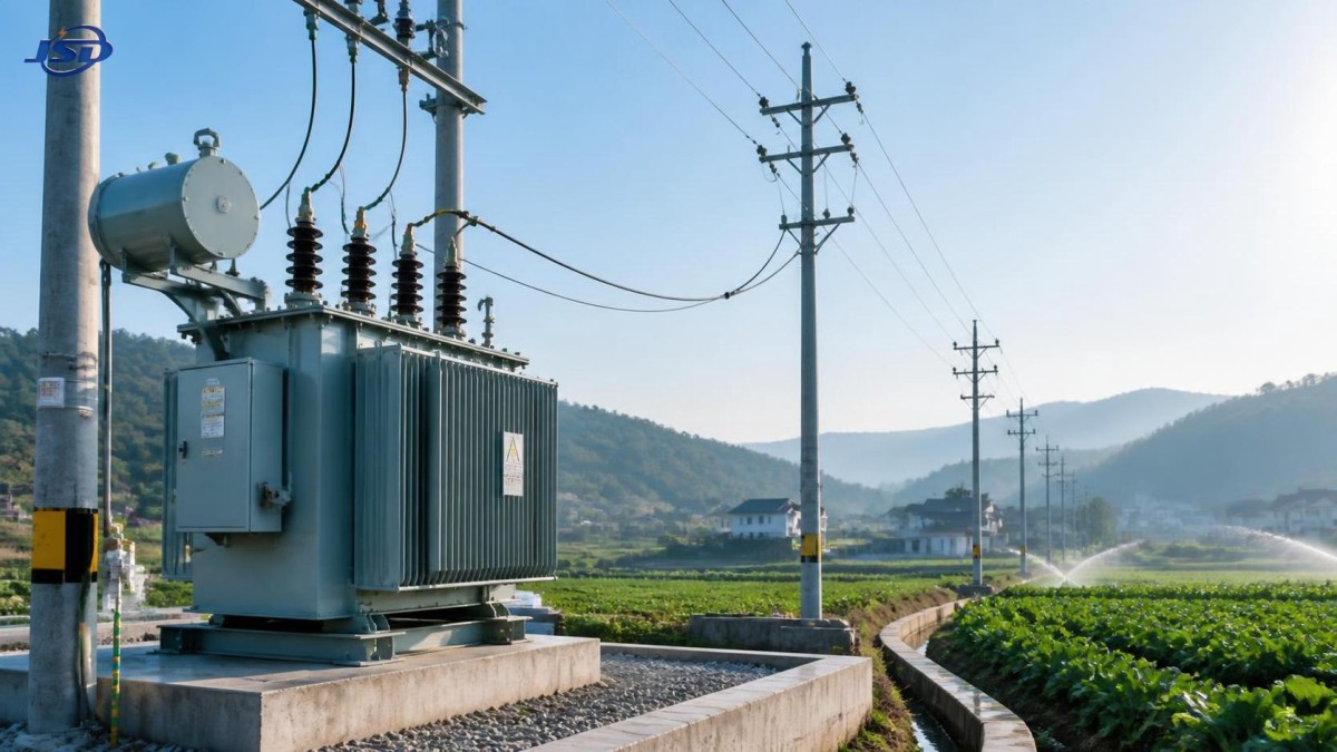
Environmental exposure should be translated into specification language. Coastal humidity, dust, flooding, high ambient temperatures, wildfire risk, and heavy vegetation each affect the preferred installation detail. For oil-filled equipment, the design team should consider containment expectations, inspection access, corrosion protection, and the availability of appropriate insulating oil handling practices. Pole-mounted, pad-mounted, and ground-mounted options should be compared against local safety rules, vandalism risk, access constraints, and outage restoration strategy.
Losses Matter More When Assets Are Widely Distributed
A rural programme may use dozens or hundreds of units. Even modest no-load losses become relevant when transformers remain energized all day while serving light loads for part of the year. Load losses, meanwhile, rise with current and become more significant where a transformer frequently operates near its expected peak. The preferred balance depends on the actual load factor, daily demand pattern, energy price assumptions, and the evaluation period used by the project owner.
This is why lowest purchase price is rarely a sufficient comparison. The tender evaluation should request comparable loss data, test documentation, efficiency requirements where applicable, and a clear statement of the operating conditions behind the figures. Core material, manufacturing control, winding design, and insulation quality influence the outcome, but the project team still needs to judge whether the offered design suits the network’s loading pattern.
For example, cold-rolled grain-oriented silicon steel cores are widely used to control magnetic losses. Careful cutting and stacking practices can also help limit no-load current and noise. On the winding side, copper high-voltage conductors and foil-wound low-voltage windings may be considered where the design objective includes sound mechanical strength and resistance to short-circuit forces. These construction details are worth reviewing in technical clarification, especially when the units will be difficult to replace.
Specification Details That Prevent Late-Stage Problems
Procurement documents should leave little room for assumptions. Besides rated power and voltage ratio, they should define frequency, vector group, tap requirements, impedance, insulation level, temperature-rise limits, accessories, terminal arrangements, enclosure or mounting configuration, applicable tests, and documentation requirements. The required standard framework must be confirmed for the destination market and utility. References such as IEC 60076 series, IEEE, ANSI, or local national requirements cannot simply be treated as interchangeable; the project specification must establish which requirements govern.
Where a rural feeder may later support workshops, mining-related facilities, civil buildings, or renewable-energy interfaces, the design should also check harmonic exposure, reverse-power possibilities, and voltage regulation needs. Not every rural installation requires these provisions, but ignoring them because the initial load is residential can create a constraint later. The right approach is to identify credible scenarios and specify only what the system actually needs.
One example for a 13.8 kV distribution network is the 13.8kV Distribution Transformer, available in ratings from 30 to 2500 kVA and designed for 50/60 Hz applications. Its configurable low-voltage outputs include common levels from 0.4 kV through 0.480 kV. That flexibility can be useful when a project includes mixed supply requirements, but voltage ratio, connection group, loss targets, and protection interfaces should still be finalized against the actual network design rather than selected from a catalogue alone.
Planning for Maintenance Before Energization
The strongest rural-grid design is one that can be maintained by the people and resources available after commissioning. This affects choices ranging from transformer location to spare-unit strategy. A remote site may justify standardized ratings and fittings across several locations, allowing one contingency unit to serve multiple installations. Clear asset labels, as-built drawings, protection settings, commissioning records, and test reports are equally valuable when fault investigation must happen quickly.
Routine attention should focus on what can be observed early: oil leakage, damaged bushings, overheated connections, abnormal sound, corrosion, loose earthing connections, vegetation clearance, and evidence of repeated fuse operation. Where the maintenance programme and equipment arrangement support it, oil condition monitoring and electrical testing can help guide intervention. The appropriate inspection interval will depend on site criticality, operating history, climate, and local procedures.
Manufacturing quality is part of this reliability equation, not a separate commercial issue. Jinshida Electric Power Technology Co., Ltd. combines technical development, manufacturing processes, and quality management to support power transmission and distribution projects across grid construction, industrial applications, new energy, and infrastructure. For project teams, the most useful supplier engagement is a technical one: confirming drawings, tests, materials, standards, delivery documentation, and service responsibilities before equipment reaches a remote site.
A Practical Decision Framework
Before approving a transformer schedule, project leaders should test the proposal against several direct questions. Does each location reflect diversified demand and realistic growth? Will the selected voltage ratio and tap arrangement hold acceptable voltage at the end of the feeder? Can the transformer withstand local lightning, fault, and ambient conditions when installed with the specified protection? Are losses being evaluated over operating life rather than ignored at purchase? And can the operator inspect, isolate, and replace the unit without an impractical field operation?
Distribution transformers for rural grids should therefore be treated as network assets rather than standalone boxes of rated capacity. A balanced design will use the smallest practical low-voltage footprint, appropriate capacity margins, durable insulation and winding construction, coordinated surge and fault protection, and documentation that supports years of operation. When these issues are resolved early, the project is far less likely to trade a low initial equipment cost for recurring voltage complaints, avoidable outages, or premature replacement work.

Get a Quote
Regardless of whether you require general advice or specific support, we are happy to help you.
Send Us Your Inquiry Today

Jinshida Electric remains committed to contributing to global energy development through professional manufacturing and superior service.