





Preventing Overheating in Three-Phase Copper-Winding Transformers in Hot Equipment Rooms
Preventing Overheating in Three-Phase Copper-Winding Transformers in Hot Equipment Rooms
Overheating in a transformer room is rarely caused by one dramatic failure. More often, it develops through a combination of ordinary conditions: a summer rise in ambient temperature, a ventilation louver blocked by dust, a new production line added without reviewing demand, or a cooling fan that is running but moving far less air than expected. For a three phase copper winding transformer, these conditions can gradually reduce thermal margin until alarms, insulation deterioration, or an unplanned trip become unavoidable.
Copper windings offer strong conductivity and are widely used where efficiency and reliable load handling matter. They are not, however, immune to heat. The winding temperature is influenced by electrical losses, airflow, room temperature, harmonic content, connection quality, and the transformer’s actual loading pattern. A unit can appear acceptable during a quick inspection while its internal hot spots are already operating closer to their limit than the external cabinet temperature suggests.
The practical objective is not simply to keep the room “cool.” It is to keep the transformer within the temperature rise and ambient conditions for which it was designed, while retaining enough margin for peak demand, fan failure, seasonal heat, and changes in adjacent equipment. This requires a maintenance approach that combines measurements, physical inspection, and operating history.
Start With the Right Temperature Question
When a high-temperature alarm appears, maintenance teams often ask whether the transformer itself is faulty. That is reasonable, but it is not the best first question. Ask instead: is the transformer producing too much heat, or is the room failing to remove normal heat? The answer determines whether the priority is load reduction, repair, ventilation work, or a more detailed electrical investigation.
Compare the room air temperature at the cooling-air inlet with the temperature around the top and rear of the transformer. If the whole room is hot, particularly near the intake path, the cooling system may be recirculating heated air. If the room is reasonable but one phase, one terminal, or one coil area is noticeably hotter than the rest, the cause is more likely localized: an unbalanced load, a loose connection, poor contact pressure, harmonic stress, or an internal issue requiring manufacturer guidance.
Do not rely on a single infrared image taken after the room door has been opened. Opening a door may temporarily alter airflow, and shiny metal surfaces can give misleading infrared readings unless emissivity is set appropriately. Use thermal imaging as a comparison tool: inspect similar phases, similar cable terminations, and repeated readings under comparable load. The trend is normally more useful than one isolated number.
Temperature protection settings also need context. A sensor alarm does not prove that the sensor has failed, and a lack of alarms does not prove that cooling is adequate. Confirm sensor locations, alarm and trip settings, fan start logic, and whether the indications are being recorded. A transformer that reaches a high temperature only during the afternoon peak may look normal during a morning service visit.
Heat in the Room Is Part of the Transformer Load
Equipment rooms are often designed around floor area, not thermal behavior. A transformer may be installed with adequate physical clearance on paper, yet still draw back its own discharge air because the exhaust route is poorly positioned. This is especially common where switchgear, cable trays, battery chargers, drives, or other heat-producing equipment share a compact electrical room.
Check the complete air path rather than only the fans. Outdoor intake louvers should be clear of debris and protected without becoming restrictive. Internal grilles, filters, and coil surfaces need cleaning. Exhaust air must have a route out of the room rather than into a ceiling void or an adjacent enclosed space. Where natural ventilation was assumed in the original design, verify that later construction work has not reduced the effective opening area.
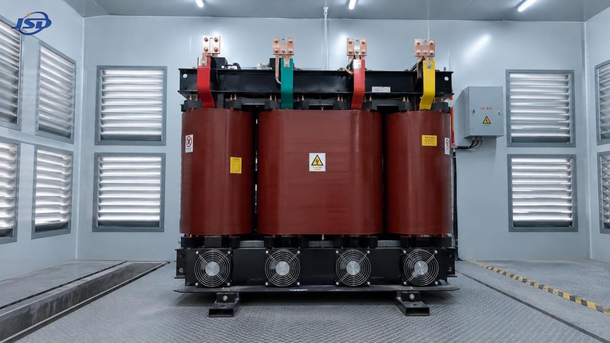
A useful field check is to observe airflow direction with safe, non-contact methods while the cooling system is operating. Dead zones behind the transformer, air short-circuiting from exhaust back to intake, and competing fan directions can become obvious quickly. Also inspect whether room doors are routinely kept closed. A door that is open during commissioning but closed during normal operation can materially change room temperature.
Forced ventilation is not automatically the answer. Oversized or poorly directed fans can pull dust through the transformer, disrupt the intended cooling path, or create a false sense of security. The better approach is to confirm the transformer manufacturer’s required clearances and cooling arrangement, then size and position room ventilation around the actual heat sources and expected ambient conditions. In very hot climates, it may be necessary to assess the room as a thermal system rather than treat ventilation as a minor building-service detail.
Review the Electrical Load Before Blaming the Cooling System
Load current should be measured on all three phases and reviewed against the transformer’s nameplate rating and cooling condition. A current reading alone is not enough. Record the time of day, ambient temperature, fan status, and major connected loads. A transformer supplying motors, welding equipment, rectifiers, UPS systems, variable-frequency drives, or rapidly changing process loads may have a thermal profile that differs significantly from a steady commercial load.
Phase imbalance deserves early attention. It can make one winding carry more thermal stress even where total kVA appears manageable. Investigate uneven single-phase distribution, poor neutral connections where applicable, and changes made during expansion work. Maintenance teams sometimes focus on the transformer while the real issue sits downstream in an unevenly loaded distribution board.
Harmonics are another frequent blind spot. Nonlinear loads can add losses and heating that are not fully revealed by a basic current clamp. If drives, data equipment, rectifiers, or other nonlinear loads have been added since installation, arrange power-quality measurement where the symptoms justify it. The review should consider current distortion, voltage distortion, neutral loading, and the transformer’s suitability for the measured duty. It is not safe to assume that a copper-wound transformer can absorb any harmonic condition merely because copper has lower resistance than some alternatives.
Voltage selection and tap position also matter. An incorrect de-energized tap setting can contribute to an unfavorable operating condition. Any tap change must follow the manufacturer’s instructions and approved isolation procedure; it is not a live adjustment and should never be treated as a quick temperature remedy. Before changing taps, confirm the actual incoming voltage and evaluate the consequences for the low-voltage system.
Inspect the Places Where Heat Starts Locally
A transformer may overheat because of a hot termination rather than overloaded windings. Inspect high- and low-voltage cable terminations, busbar interfaces, bolted joints, flexible links, grounding connections, and neutral conductors. Discoloration, insulation hardening, an unusual odor, or a temperature difference between comparable phase connections should be treated as a finding, not cosmetic aging.
Loose connections generate resistance heating, and repeated thermal cycling can worsen the condition. Re-torqueing should not be done casually: use the specified torque values, correct hardware sequence, and an appropriate outage procedure. Over-tightening can damage terminals or compromise connections just as surely as under-tightening. After corrective work, repeat the thermal inspection under meaningful load rather than assuming the issue is resolved.
For dry-type units, dust accumulation on coil surfaces and ventilation channels can also interfere with heat dissipation. Cleaning must be suitable for the insulation system and performed with the transformer safely isolated. Aggressive tools, uncontrolled compressed air, or cleaning products not approved for electrical insulation can create new problems. The aim is to remove contamination without damaging coil surfaces, sensors, insulation barriers, or connections.
Use Forced-Air Capability Correctly
Some cast-resin designs are intended to operate above their base rating when forced-air cooling is available, but this is a defined operating condition, not an unlimited reserve. The relevant nameplate data, fan arrangement, temperature-control scheme, and manufacturer documentation must govern the decision. If fan-assisted operation is permitted, verify that every fan starts automatically at the intended temperature, runs in the correct direction, and receives reliable power.
For example, the SCB10-12 configuration offered by Jinshida Electric Power is specified for operation under 120% rated load under forced-air cooling conditions and includes a temperature protection and control system. In an indoor distribution project, that capability is useful only when the room itself can reject the added heat and the control system is tested as part of routine maintenance. A suitable option for this type of application is the 11kV Three-Phase Cast Resin Dry-Type Distribution Transformer, designed for 11 kV to 0.4 kV distribution duties across a 30–2500 kVA range.
Its copper strip high-voltage winding and copper foil low-voltage winding construction, together with cast-resin insulation, suit indoor installations where fire performance and the absence of oil leakage are practical considerations. Yet no product feature removes the need to maintain clear air passages, healthy fans, clean surfaces, and correct protection settings. In service, installation conditions can matter as much as the transformer specification.
Build a Maintenance Record That Shows Deterioration Early
The best overheating prevention program is repeatable. Record phase currents, voltage, room intake temperature, transformer temperature indications, fan operation, visible cleanliness, and thermal-image observations at comparable intervals. Note process changes such as new machinery, longer production shifts, altered HVAC operation, or electrical-room modifications. These details are often what explain a temperature rise that initially seems mysterious.
A practical inspection sequence can include:
- Review temperature alarms, trips, and loading trends before entering the room.
- Measure all phase currents and identify imbalance at representative demand.
- Verify intake and exhaust airflow, fan direction, louver condition, and room recirculation.
- Thermally inspect accessible terminations, busbars, cable joints, and comparable phase points.
- Check coil and ventilation-channel cleanliness during a properly planned outage.
- Test fan control, sensor indication, alarm signaling, and trip circuits according to site procedures.
- Escalate unexplained hot spots, persistent rising trends, or insulation concerns to qualified transformer specialists.
Jinshida Electric Power Technology Co., Ltd. approaches distribution equipment through R&D, manufacturing, and application support, with attention to stable operation in industrial, infrastructure, grid, and new-energy environments. For service teams, the useful takeaway is straightforward: select equipment to match the duty, but keep installation and operating conditions under review after commissioning. Electrical rooms rarely remain unchanged for their full service life.
When a three phase copper winding transformer runs hot, avoid treating the temperature alarm as the problem itself. It is evidence. Trace whether that evidence points to ambient heat, blocked airflow, load growth, imbalance, harmonics, a failing cooling component, or a localized connection issue. Correcting the actual cause early is usually far less disruptive than waiting for insulation damage or a protection trip to force the investigation.

Get a Quote
Regardless of whether you require general advice or specific support, we are happy to help you.
Send Us Your Inquiry Today

Jinshida Electric remains committed to contributing to global energy development through professional manufacturing and superior service.