





Battery Container Design Basics: Cooling, Fire Protection, and Access Layout
Battery Container Design Basics: Cooling, Fire Protection, and Access Layout
A battery container is often described as a box full of cells, inverters, cables, and controls. In practice, that description misses the point. The enclosure is not passive. It shapes thermal behavior, influences fire propagation paths, determines how fast technicians can isolate faults, and affects whether routine maintenance is straightforward or disruptive. In utility, industrial, and infrastructure projects, these details usually matter long before a system reaches its rated capacity.
That is why cooling, fire protection, and access layout should be treated as a linked design problem rather than three separate checklists. A container that is excellent at temperature control but difficult to enter safely can become expensive to maintain. One with strong suppression hardware but weak airflow planning may still see repeated hotspots. And a layout that maximizes equipment density can quietly create service bottlenecks later, especially in projects where downtime windows are narrow.
For companies working across power transmission, distribution, and new energy applications, this systems view is familiar. Jinshida Electric Power Technology Co., Ltd., for example, operates in an environment where reliable power support depends not only on core electrical equipment, but also on how that equipment behaves under real operating conditions. In energy storage, the battery container becomes part of that reliability equation.
Cooling is not just about keeping temperatures low
When people first evaluate a battery container, they often ask a simple question: air cooling or liquid cooling? It sounds like the key decision, but the better question is how the container manages temperature uniformity. Cells do not age only because they get hot; they also age unevenly when different racks or modules run at different temperatures for long periods. That thermal imbalance can show up as reduced usable capacity, more conservative operating limits, or recurring alarms that seem random until someone maps the temperature distribution inside the enclosure.
Air cooling can work well in some applications, especially where power density is moderate and ambient conditions are not extreme. But air systems rely heavily on duct design, rack spacing, return air paths, filter condition, and the simple reality that airflow follows the path of least resistance. If one aisle is easier to cool than another, the container may look compliant on paper while still developing localized heat pockets.
Liquid cooling gives tighter thermal control and is increasingly chosen for higher-density systems. The tradeoff is obvious to anyone who has worked around electrical equipment for years: once liquid enters the design, sealing integrity, hose routing, condensate risk, service isolation, and leak detection all become part of the safety conversation. Liquid cooling is not automatically better in every project. It is usually better when the duty cycle, energy density, and ambient profile justify the added complexity.
A practical review should include more than the nominal cooling capacity. Ask where the hottest components are likely to be during peak charge and discharge, how temperature is sensed at rack level, what happens if one cooling unit fails, and whether maintenance can be done without exposing the full container to thermal drift. These are not minor details. They define whether a thermal event stays manageable or escalates into a reliability issue.
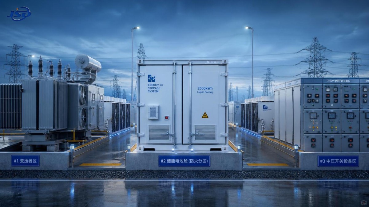
This is one reason containerized storage products built for demanding grid and industrial use often move toward integrated thermal management. A system such as 1MW/2MWh Liquid Cooling Container Energy Storage System reflects that direction, not because liquid cooling is fashionable, but because some operating profiles need more stable heat removal across the full enclosure.
Fire protection starts before suppression equipment is selected
Fire protection in a battery container is often reduced to a debate over detectors, aerosol units, gas suppression, or water-based approaches. That is only part of the story. A credible fire strategy begins with prevention and compartment behavior: how faults are detected early, how thermal runaway gases are managed, how propagation between modules is limited, and how the enclosure responds if pressure rises.
In other words, the first layer of fire protection is design discipline. Cable routing should avoid avoidable heat accumulation. Battery racks should not be packed so tightly that inspection becomes impossible. Sensitive control equipment should not be placed where smoke, corrosive gases, or heat from a single rack incident can disable the entire protection chain. Even the door opening direction and emergency egress path deserve attention, because service personnel may need to leave quickly under low-visibility conditions.
Detection also deserves more nuance than it usually gets. Smoke detection, heat detection, and off-gas monitoring do not respond at the same stage of an event. Which combination is appropriate depends on cell chemistry, rack arrangement, ventilation strategy, and the protection philosophy required by the project. This part usually needs to be checked against the applicable local code, insurer requirements, and the system integrator’s safety architecture. There is no universal template that fits every site.
Suppression itself should be judged with modest expectations. In battery incidents, suppression may control secondary fire, reduce spread, or buy time for emergency response. It may not “solve” an internal cell event in the way non-specialists imagine. That is why venting paths, compartment separation, emergency shutdown logic, and post-event access procedures should be reviewed together. A container that can detect and isolate quickly is usually in a better position than one that relies mainly on a dramatic suppression headline.
Access layout is where design theory meets daily work
Access layout sounds mundane, which is exactly why it gets underestimated. Yet many avoidable field problems start here. If technicians cannot comfortably reach breakers, valves, communications panels, sensors, and rack connection points, maintenance time increases and human error tends to follow. People improvise when the original layout is awkward. In power equipment environments, improvisation is rarely a sign of good design.
A useful battery container should allow safe movement, clear line of sight to indicators, and reasonable separation between high-voltage areas and routine service points. Emergency stop devices, fire system status panels, and BMS-related interfaces should be easy to identify without stepping deep into a potentially hazardous zone. If the project expects frequent inspection, then door placement, aisle width, lighting, and cable tray height matter more than brochure images suggest.
There is also a transport-to-operation transition that planners sometimes overlook. A container may be dimensionally efficient for shipping but awkward once installed near transformers, switchgear, fences, or fire access roads. The exterior clearance around the unit affects maintenance as much as the interior layout. If one side cannot be opened fully after installation, some replacement tasks may become far more complicated than intended.
A few layout questions worth asking early
- Can key components be isolated and serviced without shutting down the entire container?
- Are cooling units, pumps, filters, or manifolds accessible without crossing high-risk electrical zones?
- Is there enough internal and external clearance for safe replacement of modules or auxiliary equipment?
- Can operators read alarms, labels, and status indicators quickly in low-light or emergency conditions?
- Does the installed site leave room for doors, lifting paths, and emergency response access?
These questions are simple, but they tend to reveal whether a design was developed for real operation or only for factory assembly.
The transformer connection changes the conversation
In the transformer industry, battery containers are rarely standalone assets. They sit within a broader power architecture that may include step-up transformers, medium-voltage switchgear, protection panels, and site-level control systems. That proximity introduces additional design considerations. Heat sources from neighboring equipment, electromagnetic environment, cable routing distances, grounding design, and maintenance coordination all influence how the container should be configured.
For example, if the container is positioned too close to transformer cooling exhaust or in an area with poor airflow circulation, the internal thermal management system may work harder than expected. If the layout forces long DC or AC cable runs with awkward bends, installation quality may suffer. If maintenance teams for transformers and storage systems need the same access corridor, scheduling conflicts become likely during outages.
This is where companies with experience in transmission and distribution equipment have a practical advantage. They tend to view the container not as a boxed product dropped onto site, but as part of a coordinated electrical installation. That mindset usually leads to better decisions around interfaces, clearances, and long-term serviceability.
Common design mistakes that do not show up in a sales drawing
One common mistake is over-prioritizing nameplate density. A tightly packed battery container may look efficient at procurement stage, but if technicians have limited access to filters, sensors, or manifolds, routine service becomes slower and more intrusive. Another is assuming that all ambient conditions can be handled by selecting a larger HVAC unit. In reality, solar loading, dust, humidity, altitude, and door-opening frequency can all affect thermal performance in ways that a basic capacity figure does not capture.
A third mistake is treating fire protection as an add-on package. By the time suppression hardware is discussed, the enclosure geometry, rack spacing, and equipment placement may already have limited what is realistically achievable. The result is a compliant-looking system that is difficult to inspect and harder to recover after an event.
It is also worth being careful with standard language. Projects often reference international or local safety frameworks, but the exact design implications still need confirmation against the specific site, authority requirements, and integrator documentation. That review should happen early, not after the container layout is frozen.
What a good early-stage review looks like
Before selecting or approving a battery container, it helps to review five things together: expected duty cycle, local climate, fire protection philosophy, maintenance model, and site interfaces. If one of these is missing, design choices can become distorted. A container intended for frequent cycling in a hot industrial environment should not be judged by the same logic as one used for lighter backup support. Likewise, a site with restricted technician access calls for a different layout mindset than a large utility compound with dedicated service space.
In some projects, a higher-spec thermal management approach is justified because it reduces operational uncertainty over time. In others, a simpler architecture may be the better choice if the maintenance conditions are controlled and the operating profile is less demanding. The point is not to chase the most advanced feature set. It is to match the container design to the real electrical and service environment.
That same practical lens applies when looking at integrated offerings such as the 1MW/2MWh Liquid Cooling Container Energy Storage System. The value is not in the label alone, but in whether the system’s cooling logic, protection strategy, and service layout fit the project’s actual operating conditions.
A well-designed battery container does not call attention to itself every day. That is usually the best sign. It keeps temperatures stable, limits fault escalation, and lets people work safely when inspection or repair is necessary. If those basics are handled properly at the design stage, the container is far more likely to support reliable energy storage integration rather than becoming the weak point in it.

Get a Quote
Regardless of whether you require general advice or specific support, we are happy to help you.
Send Us Your Inquiry Today

Jinshida Electric remains committed to contributing to global energy development through professional manufacturing and superior service.