





How to Select a 33kV Transformer for Utility and Industrial Substations
Selecting a 33kV transformer is fundamentally a risk-management decision, not a simple exercise in matching primary and secondary voltage ratings.
Technical evaluators need a transformer that supports expected demand, withstands system faults, meets installation constraints, and remains economical throughout its operating life.
The right selection process starts with verified network data, then converts those conditions into clear electrical, thermal, insulation, protection, and commercial requirements.
For utility substations, reliability, grid compatibility, and future loading flexibility usually dominate the decision. Industrial substations often require closer scrutiny of process loads.
This guide explains how to assess a 33kV transformer systematically, helping project teams avoid undersizing, excessive losses, poor fault coordination, and avoidable operational constraints.
What Technical Evaluators Need to Confirm First
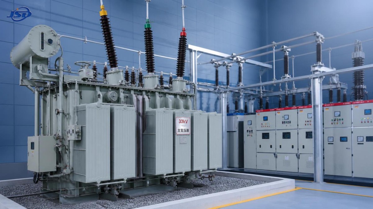
Search intent around a 33kV transformer is usually practical: evaluators want a defensible specification that will perform reliably in a defined substation application.
The first question is whether the transformer will connect a utility 33kV network to 11kV, 6.6kV, 0.4kV, or another downstream distribution voltage.
That voltage transformation duty affects winding design, insulation levels, vector group, tap range, protection settings, switchgear interfaces, and the downstream fault-current calculation.
Evaluators also need to determine whether the unit serves continuous industrial demand, a public distribution network, renewable generation, critical infrastructure, or mixed-use facilities.
A transformer supplying motors, furnaces, rectifiers, data loads, or variable-speed drives must be evaluated differently from one feeding conventional general distribution loads.
The most valuable evaluation documents are the single-line diagram, load study, short-circuit study, power-quality report, site layout, ambient conditions, and utility connection requirements.
Without those inputs, suppliers may quote technically compliant equipment that nevertheless creates voltage regulation problems, unavailable capacity, or difficult protection coordination after commissioning.
Therefore, use the titleplate rating as the outcome of engineering analysis, rather than treating it as the starting point for selecting a 33kV transformer.
Start With Load Profile and Required Capacity
Rated capacity should cover the maximum diversified demand while allowing for foreseeable growth, operating overloads, ambient temperature effects, and the transformer cooling capability.
Do not size solely from installed connected load. Calculate coincident peak demand using actual operating schedules, demand factors, load diversity, and documented expansion plans.
For industrial facilities, establish whether large motors start across the line, whether multiple loads can start together, and whether process duty is continuous.
Motor starting can cause substantial voltage dip. A transformer with marginal capacity or unsuitable impedance may disrupt sensitive controls and prevent reliable equipment acceleration.
Nonlinear loads require separate analysis because harmonics increase winding eddy-current losses, generate additional heat, and can reduce the usable continuous transformer capacity.
Where load forecasts are uncertain, compare one larger transformer with a parallel-transformer arrangement. Redundancy can improve availability but requires careful impedance and tap coordination.
Utilities commonly evaluate normal loading, emergency loading, and loss-of-one-transformer conditions. The required rating may differ significantly across these operating scenarios.
Ask the manufacturer to state the applicable loading standard, reference ambient temperature, winding hot-spot limits, and permitted overload profile in the technical proposal.
A realistic capacity selection balances capital expenditure against outage exposure. Excessively conservative sizing can create unnecessary no-load losses and poor asset utilization.
Define Voltage Ratings, Taps, and Vector Group Precisely
A 33kV transformer must be specified using the actual highest system voltage, nominal voltage, frequency, insulation requirements, and the intended secondary operating voltage.
Confirm whether the 33kV system is nominally 33kV with equipment rated for 36kV, as this distinction directly affects insulation coordination and terminal design.
The secondary voltage should reflect real busbar requirements under load, rather than simply copying a nominal switchgear voltage from an earlier project document.
Tap changers compensate for supply-voltage variation and loading conditions. The appropriate tap range depends on utility regulation practice, feeder length, and downstream voltage tolerance.
An off-circuit tap changer is suitable where voltage is stable and infrequent adjustment is acceptable. An on-load tap changer supports continuous voltage regulation.
For an on-load tap changer, evaluate tap range, step size, diverter-switch duty, control logic, parallel operation requirements, and maintenance access before finalizing the specification.
Vector group selection determines phase displacement and grounding behavior. It must align with existing transformers, protection schemes, harmonic management, and parallel operating requirements.
A delta winding can provide a path for triplen harmonics, while a grounded star winding may provide the neutral connection required by the downstream distribution system.
Never select vector group from a catalog convention alone. Confirm phase relationships against the complete substation single-line diagram and all possible backfeed operating states.
Match Impedance to Fault Level and Voltage Regulation
Transformer impedance is one of the most consequential 33kV transformer parameters because it controls secondary fault current, voltage drop, and parallel-load sharing behavior.
Lower impedance generally produces higher fault current and improved voltage regulation, but it can exceed switchgear interrupting ratings or increase mechanical fault stresses.
Higher impedance restricts fault current and can reduce switchgear costs, but excessive impedance may create unacceptable voltage dip during motor starting or peak demand.
Use short-circuit studies to calculate prospective fault levels at each busbar. Include upstream network contribution, generator contribution, motor contribution, and transformer impedance tolerance.
The stated impedance should include its manufacturing tolerance. Small deviations can materially affect parallel operation and protection coordination in large industrial or utility substations.
When transformers will operate in parallel, their voltage ratios, vector groups, impedance percentages, impedance angles, tap positions, and ratings must be compatible.
Unmatched units do not share load predictably. One transformer can become overloaded before the combined bank reaches its apparent total nameplate capacity.
Specify short-circuit withstand capability separately from impedance. The transformer must tolerate calculated external fault currents for the required duration without permanent mechanical damage.
Technical bid comparisons should show impedance at rated capacity and the related system study assumptions, not merely a single percentage copied into a datasheet.
Select Insulation, Cooling, and Construction for the Site
Transformer construction should reflect the installation environment, fire strategy, maintenance resources, space limitations, altitude, pollution level, seismic risk, and ambient temperature range.
Oil-immersed transformers are widely used outdoors because they offer high ratings, effective cooling, and proven long-term performance when oil containment is properly managed.
Dry-type transformers can be preferable for indoor substations, buildings, tunnels, and locations where fire safety, reduced maintenance, and no oil-leakage risk are priorities.
For secondary indoor distribution applications, an 11kV Three-Phase Cast Resin Dry-Type Distribution Transformer can provide a practical oil-free solution after the 33kV transformation stage.
Cast-resin designs use encapsulated windings to improve resistance to moisture, dust, and fire exposure. Their suitability still depends on ventilation and thermal conditions.
Cooling designation defines the available thermal performance. Common oil-immersed arrangements include ONAN, ONAF, OFAF, and OFWF, each with different auxiliary requirements.
Forced-air cooling can increase available capacity, but fans introduce maintenance needs, noise, control dependencies, and a reduced rating when auxiliary cooling is unavailable.
Check the guaranteed rating for each cooling stage. Do not assume the highest forced-cooling rating remains available during fan failure or station auxiliary-power loss.
High-altitude sites require derating or enhanced insulation design because lower air density affects cooling performance and external dielectric withstand capability.
Evaluate Losses as a Lifecycle Cost, Not a Datasheet Detail
Transformer losses are paid for throughout the asset life. A low purchase price can become expensive when no-load and load losses remain high for decades.
No-load loss occurs whenever the transformer is energized, regardless of load. It is especially important for lightly loaded utility assets operating continuously.
Load loss increases approximately with the square of current. It becomes more significant for heavily loaded industrial transformers and assets carrying sustained process demand.
Compare guaranteed loss values at the relevant operating point, then apply the project energy price, expected annual loading profile, and anticipated service duration.
A useful evaluation considers capitalized losses, not only quoted equipment cost. This assigns a monetary value to each watt of no-load and load loss.
Efficiency should be assessed at realistic load levels. A transformer optimized for full-load efficiency may not deliver the best annual energy performance at partial load.
Core material, conductor selection, winding geometry, and manufacturing quality influence loss performance. Guaranteed values should be supported by routine factory test results.
Also assess auxiliary consumption from cooling fans, oil pumps, tap-changer controls, heaters, and monitoring equipment, particularly for continuously operated substations.
Specify Protection, Monitoring, and Test Requirements
A dependable transformer installation requires coordinated electrical protection, mechanical protection, temperature supervision, and alarm reporting suited to the criticality of the load.
Typical protection may include differential protection, restricted earth fault protection, overcurrent protection, earth fault protection, Buchholz protection, and pressure-relief devices.
Oil temperature, winding temperature, oil level, pressure, cooling-fan status, and tap-changer position should be monitored where operational consequences justify the investment.
For critical utility assets, online dissolved-gas analysis and bushing monitoring can help identify developing insulation faults before they become forced outages.
Protection settings should be developed using the actual transformer vector group, neutral grounding arrangement, inrush behavior, impedance, and upstream and downstream fault levels.
Factory acceptance testing should include routine tests required by applicable standards, including ratio, polarity, vector group, winding resistance, impedance, losses, and dielectric testing.
For higher-risk projects, request type-test evidence, temperature-rise data, lightning impulse capability, short-circuit withstand evidence, and independent quality documentation where applicable.
Standards such as IEC 60076 provide a strong technical baseline, but project specifications should add site-specific requirements rather than relying on standards alone.
Use a Structured Technical Bid Evaluation
Build a weighted evaluation matrix before receiving quotations. This prevents price from overwhelming requirements related to reliability, losses, delivery, maintainability, and compliance.
Mandatory checks should include rated power, voltage ratio, tap changer, vector group, impedance, insulation level, cooling class, terminal arrangement, and dimensional limitations.
Then compare guaranteed losses, temperature rise, sound level, auxiliary consumption, overload capability, protection interfaces, accessories, and spare-parts recommendations.
Review the supplier’s manufacturing controls, test facilities, references in similar duties, quality certifications, service capability, and response process for technical issues.
For a 33kV transformer, clarify responsibility boundaries between transformer supplier, civil contractor, switchgear supplier, protection engineer, and commissioning team early.
Those boundaries should cover cable boxes, bushings, neutral grounding equipment, marshalling panels, control cables, oil containment, fire systems, and remote monitoring integration.
Request guaranteed delivery documents, drawings, test reports, installation instructions, maintenance schedules, and recommended critical spares as part of the contractual scope.
Jinshida Electric Power Technology supports power-distribution projects with engineering-focused manufacturing, quality management, and equipment solutions for industrial, utility, infrastructure, and new-energy applications.
Conclusion: Select for the System, Not Only the Nameplate
The best 33kV transformer selection is based on the complete power system: load behavior, voltage regulation, fault duty, environment, protection philosophy, and lifecycle economics.
Capacity and voltage ratio are essential, but impedance, taps, vector group, insulation coordination, cooling resilience, and guaranteed losses frequently determine long-term project success.
Technical evaluators should require documented studies, measurable guarantees, and clear acceptance tests before approving a supplier or releasing the final transformer specification.
A disciplined evaluation process produces a transformer that fits the substation, protects connected equipment, controls operating cost, and supports reliable future expansion.

Get a Quote
Regardless of whether you require general advice or specific support, we are happy to help you.
Send Us Your Inquiry Today

Jinshida Electric remains committed to contributing to global energy development through professional manufacturing and superior service.