





Acceptance Tests for Substation Transformers Installed at Solar Farms
Acceptance Tests for Substation Transformers Installed at Solar Farms
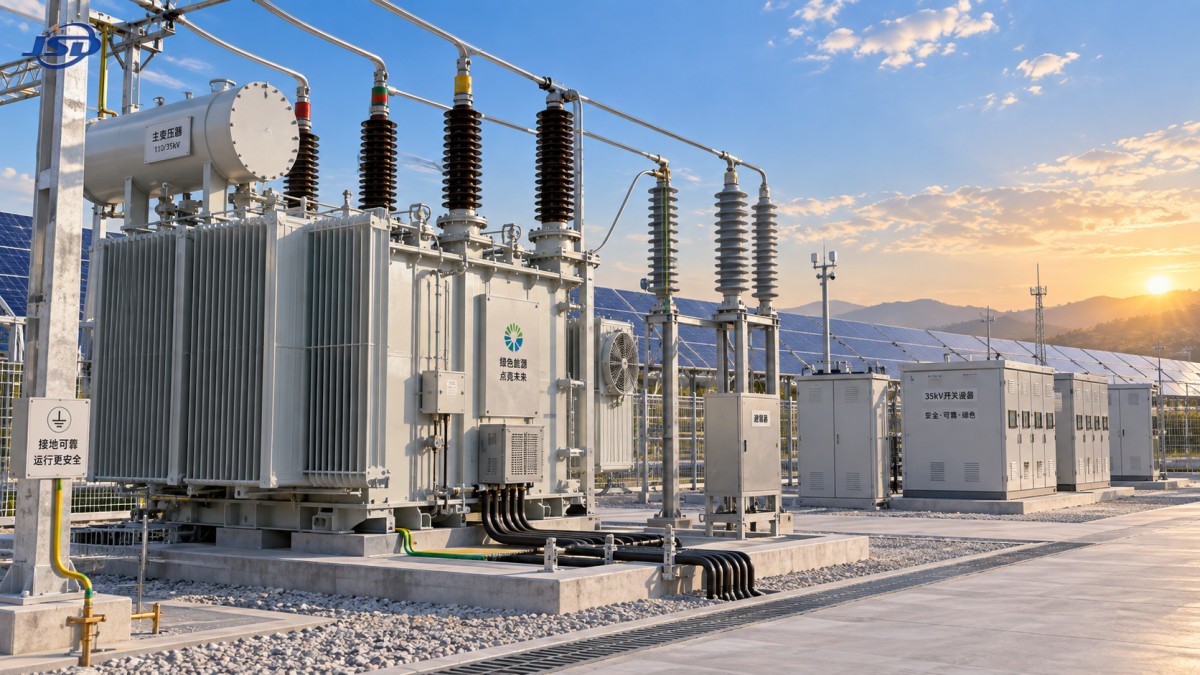
Acceptance testing is the point at which a solar project moves from installed equipment to a controlled electrical system ready for energization. For a substation transformer for solar farms, the process is not limited to proving that the unit has arrived without visible damage. It must confirm that transportation, storage, assembly, cable work, grounding, protection settings, and the transformer’s electrical condition all remain consistent with the approved design.
This matters because solar plant loading is not always gentle or predictable. Inverter switching, daily generation ramps, reactive-power requirements, high ambient temperatures, dust, moisture, and long collector circuits can expose weaknesses that were not obvious during factory testing. A transformer can pass routine factory tests and still present site risks if its installation interfaces, insulation condition, cooling arrangement, or protection scheme are not properly checked before commissioning.
For quality-control and safety teams, the most useful acceptance program is evidence-based. It starts with approved drawings and factory records, then compares them with what is physically installed and electrically measured on site. The goal is to identify deviations while they can still be corrected safely, rather than discovering them during grid synchronization or after a forced outage.
Begin with document control, not test instruments
A disciplined handover begins by confirming the transformer identity and intended duty. Nameplate data should match the approved equipment schedule: rated power, high- and low-voltage ratings, frequency, vector group, impedance information where specified, cooling class, tap range, insulation level, and applicable standard. IEC 60076 is commonly used as a reference framework for power transformers, but project specifications, local grid requirements, and the manufacturer’s instructions may impose additional conditions.
The acceptance dossier should normally include the factory test report, routine test records, shipping and preservation records, drawings, terminal arrangement details, manuals, oil documentation for liquid-filled units, and certificates or calibration records for relevant accessories. Review these before site testing. A missing factory report does not automatically mean the transformer is defective, but it does weaken traceability and makes later interpretation of site results more difficult.
One frequent problem is treating the transformer as an isolated package. In a solar substation, its vector group and neutral treatment affect relay coordination, metering, harmonic behavior, inverter transformer interfaces, and fault-current paths. A mismatch may be physically difficult to notice but electrically consequential. The approved single-line diagram, protection philosophy, and relay setting file should therefore be part of the acceptance review.
Installation inspection: catch the practical failures first
Before applying test voltage, inspect the installation in daylight and compare it with approved drawings. Look for transit damage, oil leakage, cracked bushings, loose fittings, incomplete radiators, damaged cable boxes, missing labels, and signs that moisture or dust has entered open compartments. If the transformer was stored on site, verify that preservation arrangements followed the manufacturer’s requirements. Prolonged storage, especially in humid or highly variable climates, deserves more scrutiny than a short, controlled installation interval.
Mechanical checks should include foundation condition, anchoring, clearances, access routes, lifting points, fire separation measures where required, drainage, and the integrity of the transformer enclosure or marshalling cabinet. Outdoor solar installations also need a practical review of weather exposure. Cable glands, control cabinets, fan motors, radiator valves, breather assemblies, and sealing surfaces should be suitable for the site environment and properly closed before energization.
Grounding is often inspected visually but insufficiently verified. Confirm that the tank, neutral point where applicable, surge arresters, cable screens, control panels, and nearby metallic structures are connected according to the grounding design. The relevant continuity and earth-resistance checks should be evaluated against the project’s approved criteria, not against an assumed universal value. Soil conditions and grid design make this a site-specific assessment.
Core electrical tests and what they reveal
Site tests should be selected according to transformer type, voltage class, contractual requirements, time out of service, transport conditions, and the manufacturer’s recommendations. The purpose is not simply to collect readings. Every reading needs a reference: factory values, prior baseline data, instrument correction, test temperature, or an acceptance criterion defined in the project documentation.
Insulation resistance and polarization behavior
Insulation-resistance testing helps identify moisture, contamination, damaged insulation, or inadequate drying. It is commonly performed between windings and earth, with test voltage and duration selected for the equipment and procedure. A single resistance number should not be interpreted in isolation. Temperature, humidity, transformer size, insulation construction, and prior readings influence the result. Where polarization index or similar time-based observations are specified, they can provide additional context, but they do not replace a full condition assessment when results appear abnormal.
Turns ratio, vector group, and tap-position verification
Transformer turns-ratio testing verifies whether the measured voltage ratio corresponds to the nameplate and selected tap. It should be carried out across relevant tap positions. This test is particularly useful after transport or tap-changer work because it can expose incorrect connections, winding issues, or a tap mechanism that does not reach the expected position.
Vector-group confirmation is equally important. A phase displacement or polarity error can create serious commissioning problems when the transformer is connected to inverter stations, collector feeders, or a utility substation. The test team should verify phase identification from transformer terminals through cables and switchgear, rather than assuming labels were preserved correctly through installation.
Winding resistance and magnetic balance checks
Winding-resistance measurements can reveal poor bolted joints, damaged conductors, tap-changer contact problems, or unbalanced phase conditions. Results should be compared among phases and, where possible, with factory records after appropriate consideration of temperature. The test must be allowed to stabilize; rushed readings are a common source of misleading conclusions.
Magnetic balance testing may also be used where appropriate to check core and winding behavior. It should be interpreted by competent personnel because different transformer designs can produce different expected patterns. An unusual result is a reason to investigate, not an automatic diagnosis by itself.
Oil and dielectric condition for liquid-filled units
For oil-filled transformers, an oil sample can provide valuable acceptance evidence, particularly after long transport, site storage, or field assembly. Depending on the agreed procedure, testing may consider dielectric strength, moisture, acidity, and dissolved gases. These tests need careful sampling discipline. A contaminated bottle, poor sampling point, or unrepresentative sample can create confusion rather than clarity.
Oil results should be reviewed alongside physical inspection, insulation measurements, and any gas relay or pressure-relief observations. They are not a substitute for confirming that valves are in their correct service positions, oil levels are appropriate, and cooling circuits are complete.
Protection, control, and cooling must be tested as a system
A substation transformer for solar farms is accepted only when its associated protection and control circuits operate as intended. This includes checks of differential protection where installed, overcurrent and earth-fault functions, temperature alarms and trips, pressure or gas-operated devices, oil-level contacts, fan controls, local/remote indications, trip-circuit supervision, and interlocking logic. The exact arrangement depends on the project design, so acceptance should follow approved cause-and-effect documentation and relay settings rather than a generic checklist.
Secondary injection and functional testing should verify not just that a relay operates, but that the correct circuit breaker receives the trip command, alarms reach the expected supervisory system, and blocking or intertrip signals behave correctly. Incorrect terminal wiring and untested control logic have caused many avoidable delays at commissioning, even where primary equipment was in good condition.
Cooling deserves the same attention. Confirm fan rotation, automatic and manual control modes, alarm points, pump operation where applicable, and loss-of-supply indications. Solar plants may see high daytime ambient temperatures at the same time as strong generation. A cooling circuit that is mechanically present but electrically unproven is not an acceptable handover condition.
Do not overlook cables, surge protection, and inverter-side interfaces
Transformer tests alone cannot validate the entire connection. Cable insulation tests, sheath tests where specified, phase continuity, termination torque records, screen grounding, and cable identification should be reviewed as part of the same acceptance package. Verify that surge arresters have the correct ratings for the system design and that their grounding leads are short, direct, and securely connected in accordance with the installation arrangement.
The inverter-side connection deserves a final design review. Confirm rated voltage compatibility, vector group, earthing arrangement, tap setting, and any grid-code-driven reactive-power or voltage-control assumptions. A tap position suitable for a factory default may not be suitable for the actual collector-system voltage profile. Tap selection should be approved by the project electrical authority and recorded before energization.
Equipment experience from other renewable applications can be useful when evaluating environmental durability and continuous operation. For example, outdoor units designed for new-energy duties may use three-phase configurations, copper windings, ONAN or ONAF cooling, and IEC 60076-based design principles. The published configuration of a Transformer for Wind Power Generation, including 0.69 kV low-voltage options and 10 kV, 20 kV, or 35 kV high-voltage arrangements, illustrates why acceptance criteria must always be tied to the actual project’s voltage interface and connection scheme rather than borrowed from another renewable project.
A handover record that can support future troubleshooting
The final acceptance record should be practical enough to use years later. It should identify the transformer and test instruments, state test dates and environmental conditions where relevant, include raw and corrected readings, record the tap position, identify open items, and show who reviewed and accepted each stage. Photographs of terminal markings, grounding connections, accessory settings, and nameplates can be valuable when site teams change.
Jinshida Electric Power Technology Co., Ltd. approaches power-equipment delivery with the understanding that manufacturing quality and site acceptance are connected. Advanced manufacturing processes and rigorous quality management establish a reliable starting point, but dependable service in grid, industrial, and renewable projects also depends on clear technical documents, correct installation, and disciplined commissioning records.
Before energization, unresolved findings should be classified by operational and safety consequence, assigned to a responsible party, and formally closed. The strongest acceptance test is not the longest checklist. It is a coherent body of evidence showing that the transformer, its protection, its grounding, and its grid connection have been verified against the design that the solar farm is actually going to operate.

Get a Quote
Regardless of whether you require general advice or specific support, we are happy to help you.
Send Us Your Inquiry Today

Jinshida Electric remains committed to contributing to global energy development through professional manufacturing and superior service.