





Electrical Substation Transformer Standards for Factory Acceptance Testing
Late in the factory test schedule, an electrical substation transformer may appear ready for shipment: the tank is painted, terminals are fitted, accessories are installed, and the nameplate matches the purchase order. Then a test record raises a question. A winding-resistance value does not trend as expected across tap positions, a no-load loss result needs clarification, or an insulation reading is presented without the temperature correction method. At that point, the issue is no longer simply “pass or fail.” It becomes a question of whether the test was performed under the right standard, with the right connections, and against the right acceptance basis.
This is a familiar pressure point before factory acceptance testing (FAT). A transformer that leaves the factory with incomplete evidence, unresolved deviations, or poorly controlled test procedures can create commissioning delays and difficult accountability discussions later. For an electrical substation transformer, FAT is the practical barrier between manufacturing completion and safe installation. The most useful approach is to treat standards as a framework for decisions, not as a stack of documents to be cited after testing is finished.
Start by identifying which standard actually governs the order
The first mistake in FAT preparation is assuming that every transformer is tested to one universal rulebook. Transformer standards are related, but they do not automatically replace one another. The applicable requirements normally come from the purchase specification, contract documents, approved drawings, nameplate data, grid or project requirements, and the standard edition identified in the order.
For many international projects, the IEC 60076 series provides the central technical basis for power transformer design, ratings, dielectric requirements, temperature-rise evaluation, losses, and test classification. In projects using North American practice, IEEE C57 standards and applicable customer specifications may define test methods, tolerances, documentation, and witness requirements differently. Local grid codes or utility requirements can add further conditions, especially for voltage ratio, impedance, sound level, accessory interfaces, protection devices, and oil handling.
Before the test bay is booked, the responsible team should establish a controlled test basis containing the following information:
- Transformer rating, voltage ratio, frequency, vector group, impedance, tap range, cooling modes, and insulation levels;
- The governing standard and its referenced parts;
- Contractual guaranteed values, including losses where applicable;
- Required routine, type, special, and additional tests;
- Witness, hold-point, notification, and release requirements;
- Approved drawings for terminals, bushings, tap changer, cooling equipment, and protection accessories;
- Rules for deviation handling, retesting, and final report approval.
That controlled basis is more valuable than a generic test plan. It prevents a common disagreement: one side expects a test because it is customary on similar units, while the other side considers it outside the contracted scope. If a requested test is not clearly covered, the right response is to clarify its purpose, method, timing, and acceptance criterion before the transformer is energized in the test bay.
Routine tests are not merely a paperwork exercise
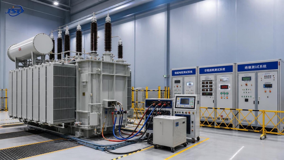
Routine tests are generally performed on each manufactured unit to verify that key electrical and functional characteristics meet the applicable requirements. The exact list depends on the transformer design and governing standard, but FAT for an electrical substation transformer commonly includes measurement of winding resistance, voltage ratio and phase displacement, short-circuit impedance and load loss, no-load loss and current, dielectric tests, and verification of the tap changer and auxiliary equipment.
A routine test result should always be read with its conditions. For example, winding resistance values are temperature dependent. Comparing a measurement taken at one winding temperature with a previous value taken under a different condition can produce an apparent discrepancy that is not a manufacturing defect. The report should identify the measured temperature, the correction method when used, the tap position, the test current or instrument method, and the winding terminals involved.
Voltage-ratio testing requires similar discipline. The test should cover the relevant tap positions and confirm the specified ratio, polarity, and vector group. An incorrect phase displacement can affect parallel operation, protection coordination, metering, and system energization. A result reported only as “ratio acceptable” is less useful than a traceable record showing the selected tap, measured ratio, specified ratio, and tolerance basis.
No-load and load-loss tests deserve close review because their interpretation links directly to the contractual guarantee. Confirm that the test arrangement, voltage and frequency conditions, corrections, and calculation method are documented. If a result is close to a guarantee limit, the report should make the applied standard and correction treatment transparent rather than relying on a summary statement.
Dielectric testing needs more than a final pass indication
Dielectric tests are often the most closely watched FAT activity because they assess the transformer insulation system under specified electrical stress. Depending on the design and standard, the test program may include applied-voltage tests, induced-voltage tests, lightning impulse tests, switching impulse tests, or other specified dielectric examinations.
The required test level is not selected by preference. It is related to the system voltage, insulation level, terminal arrangement, transformer category, and contractual requirements. Before the test begins, confirm that the test connection diagram corresponds to the actual transformer configuration. Neutral grounding arrangements, tertiary windings, bushing terminals, screened leads, and disconnected accessories can materially affect the setup.
During review, look beyond a single “passed” entry. A complete dielectric test record should show the applied test voltage, duration where relevant, frequency or waveform, test circuit arrangement, instrument references, and observations made during the test. For impulse testing, recorded waveforms and their interpretation are particularly important. A waveform difference should not be dismissed automatically, but neither should it be treated as a failure without technical comparison against the reference traces and the applicable evaluation method.
Partial discharge requirements should also be handled carefully. Where specified, the test report should identify the test voltage sequence, background conditions, measuring arrangement, calibration information, and measured values. A low reading alone does not prove that the process was sound if noise, grounding, calibration, or test-circuit conditions were not controlled.
Where FAT reviews often go wrong
A frequent misconception is that a certificate of conformity can replace raw test evidence. Certificates have a role, but they do not explain how a particular unit was tested. For critical characteristics, the purchaser or appointed reviewer needs traceability from the nameplate and approved design through the actual measurements and final report.
Another weak practice is reviewing results without checking identity. The serial number, manufacturing number, test date, drawing revision, tap changer identity, bushing arrangement, and accessory configuration should all correspond to the delivered unit. This is especially relevant when a factory handles several similar transformers at the same time. A technically correct report attached to the wrong unit is still an acceptance risk.
It is also risky to treat all deviations as equivalent. Some issues are administrative, such as an omitted calibration reference or unclear terminal label. Others may affect dielectric integrity, thermal performance, transport readiness, or safe site operation. A useful deviation record describes the requirement, the observed condition, technical assessment, proposed action, responsible party, evidence of closure, and whether retesting is necessary. “Closed” should mean that the agreed evidence is available, not simply that the issue is no longer discussed.
A practical sequence for reviewing the test package
Begin with the approved technical data. Verify that the rating plate information matches the order: rated power, primary and secondary voltages, frequency, vector group, cooling designation, impedance, tap range, and insulation levels. Then compare the final arrangement drawing with the physical unit. Check terminal markings, bushing locations, marshalling box interfaces, oil level indicators, pressure-relief equipment, temperature devices, cooling fans or pumps where fitted, and grounding points.
Next, review the test plan against the contractual test schedule. Do this before examining individual values. It is easier to identify a missing test at this stage than after shipment release paperwork has started. The review should distinguish between tests completed on the unit, tests supported by valid design evidence where permitted, and tests not applicable to the supplied configuration.
Then assess each report for repeatability and traceability. The measurement method, test equipment identification, calibration status, ambient or winding condition, terminal connection, and tap position should be sufficiently recorded for another qualified reviewer to understand the result. A short report can be acceptable if it is clear; a large report with unexplained tables is not automatically stronger evidence.
Finally, inspect the release documentation as an integrated package. This normally includes the approved drawings, nameplate record, routine test reports, oil-related records when applicable, accessory test information, packing or preservation instructions, transport constraints, and any agreed deviation closure documents. The objective is not to create unnecessary paperwork. It is to ensure that the information needed for installation, commissioning, and future maintenance is not lost between factory and site.
Special attention for renewable-energy step-up applications
Transformers used between inverter systems and the grid may require closer discussion of operating conditions than a conventional steady-load installation. Harmonic content, load cycling, ambient exposure, connection requirements, and tap selection should be aligned with the project design. These conditions do not automatically change every FAT requirement, but they can affect the specification and the evidence expected before release.
For example, a Step-Up Transformer for Photovoltaic Power Stations may be configured for 500kVA–5000kVA duty, with high-voltage options of 10kV, 20kV, or 35kV and low-voltage options including 0.315kV, 0.4kV, and 0.69kV. Such a transformer may use Dyn11 or Yyn0 vector groups, ONAN or ONAF cooling, and specified tap ranges. During FAT, those selections must be checked against the approved project configuration rather than assumed from a product family description.
IEC 60076 is identified for this type of photovoltaic step-up transformer, but the purchase specification should still state the exact tests required for the supplied unit. In particular, verify the low-voltage winding voltage against the inverter output design, confirm the high-voltage side matches the grid connection arrangement, and make sure tap positions are documented in a way that supports commissioning. Copper winding material, outdoor installation design, and stated cooling mode are also details that should align across drawings, nameplate, inspection records, and test documents.
When a result needs investigation instead of immediate rejection
Not every unexpected value signals a defective transformer. Measurement uncertainty, temperature variation, test lead resistance, tap position error, incorrect reference data, or an incomplete calculation can all create an apparent problem. The right first step is to preserve the original record and verify the test setup. Repeating a test without understanding the initial conditions can remove useful diagnostic information.
Ask a focused set of questions: Was the correct unit connected? Were terminals identified properly? Was the tap changer in the stated position? Were instruments within calibration? Was the relevant temperature recorded? Does the applicable standard require a correction or comparison method? Is the result inconsistent with related tests, or only with an assumed expectation?
If the issue remains unresolved, request a technical explanation supported by revised calculations, repeated testing under controlled conditions, or additional inspection as appropriate. Retesting should use an agreed procedure and should not overwrite the original result. Both records should remain in the quality file, with a clear explanation of why the repeat was needed and which result is accepted.
Release only when the evidence supports safe next steps
A sound FAT release does not mean that site commissioning can be skipped. Shipping, storage, oil processing, installation, cable connection, grounding, protection settings, and site tests still introduce their own risks. However, a disciplined factory review gives the installation team a dependable baseline and reduces uncertainty when later measurements are compared.
For every electrical substation transformer, the most defensible acceptance decision comes from matching the actual unit, the contractual requirements, the governing standard, and the recorded test conditions. When those four elements agree, FAT becomes more than a final factory formality. It becomes a controlled handover of technical evidence that supports safer energization and more reliable service.
Hot News
- 00
0000-00
How U.S. DOE efficiency rules affect distribution transformer manufacturers - 00
0000-00
How american type pad mounted transformer seismic qualification affects installation in California utility grids? - 00
0000-00
Do european compact substation transformer EMC compliance tests include conducted emissions up to 30MHz?
0000-00
Contact Us

Get a Quote
Regardless of whether you require general advice or specific support, we are happy to help you.
Send Us Your Inquiry Today

Jinshida Electric remains committed to contributing to global energy development through professional manufacturing and superior service.