





Utility Transformer Selection for Peak Loads, Grid Reliability, and Expansion
The Selection Question Is Bigger Than Nameplate Capacity
Selecting a utility transformer is not simply a matter of matching kVA or MVA ratings to a forecast load. For utility operators, industrial developers, infrastructure investors, and EPC decision-makers, the transformer sits at the point where demand growth, network reliability, asset life, and capital discipline meet. A unit that appears adequately rated on a planning spreadsheet can still become a constraint if its cooling arrangement, impedance, tap range, insulation system, site conditions, or delivery plan do not match the actual operating environment.
The practical question is therefore not, “What transformer size is needed today?” It is, “What transformer configuration will support the expected duty cycle, preserve acceptable service continuity, and leave realistic options for expansion without creating unnecessary lifecycle cost?” That distinction matters most where peak demand is rising faster than average demand, where renewable generation changes load flow, or where outage consequences are commercially significant.
Decision-makers should treat transformer selection as a network and asset-management decision. The right choice depends on how the transformer will be loaded, what happens during a contingency, how quickly load may change, and whether the surrounding substation has room and protection capacity for future development.
Start With the Load Shape, Not the Annual Energy Forecast
Annual consumption can conceal the conditions that determine transformer stress. A site may have moderate yearly energy use while imposing short, repeated peaks that drive thermal aging and constrain operational flexibility. Electrified industrial processes, data-intensive facilities, rail systems, charging hubs, irrigation loads, and mixed-use developments commonly have demand profiles that are far less stable than conventional planning assumptions suggest.
A credible selection process begins with interval load data where it is available. Where the project is new, planners should construct several defensible demand cases rather than rely on a single “expected” load figure:
- Normal operating demand, including seasonal variation and forecast load diversity.
- Firm peak demand under credible high-use conditions.
- Contingency loading when another transformer, feeder, or distributed resource is unavailable.
- Ramp conditions caused by industrial starts, solar output changes, battery charging, or large blocks of flexible demand.
- Expansion demand, separated into committed load and speculative load.
This approach prevents a common procurement error: purchasing for the average future load while assuming that cooling and short-duration overload capability will solve the peak problem. Emergency and cyclic loading can be technically acceptable under defined conditions, but it is not free capacity. It affects insulation aging, maintenance priorities, and the margin available when ambient temperature is high or a parallel unit is out of service.
Loading studies should identify both the magnitude and duration of peak events. A transformer that experiences one brief winter evening peak has a different design requirement from one that runs near its thermal limit for hours each day through a hot season. The latter may justify a larger unit, enhanced cooling, a different loading profile, or a network-level demand-management measure.
It is also important to distinguish customer-connected capacity from coincident demand. Connected load is useful for identifying the scale of possible expansion, but it should not be substituted for a diversity-based demand assessment. The reverse mistake is equally risky: applying historical diversity factors to a development where EV charging, electric heating, storage, or synchronized industrial equipment reduces diversity in practice.
Peak Capacity Must Be Evaluated Alongside Reliability
A higher-rated transformer does not automatically make a network more reliable. Reliability depends on the transformer, but also on substation arrangement, bus configuration, feeder alternatives, protection coordination, spare strategy, and the time required to restore service after failure. A single large unit may be efficient in capital terms, yet it can create a high-consequence failure point if no alternate supply or replacement plan exists.
For critical loads, the central question is often whether the design can satisfy an N-1 condition, meaning that the loss of one major component can be managed without unacceptable interruption. The answer may involve two transformers operating in parallel, a normally open network tie, mobile transformer provisions, selective load shedding, or contractual backup arrangements. The best configuration is driven by outage tolerance, not by a generic preference for one large transformer or two smaller ones.
Parallel transformer schemes deserve particular attention. They can improve operational resilience and make staged expansion easier, but only when voltage ratio, vector group, impedance characteristics, tap settings, and protection arrangements are compatible. Poor matching can create circulating currents or uneven load sharing. Buyers should not assume that two units with broadly similar ratings will operate well in parallel without an engineering review.
Reliability evaluation should also include maintainability. Consider access for inspection, oil sampling, bushing replacement, cooling equipment service, relay testing, and eventual transformer removal. A technically sound transformer can become an operational burden if the site layout makes routine work disruptive or major replacement impractical.
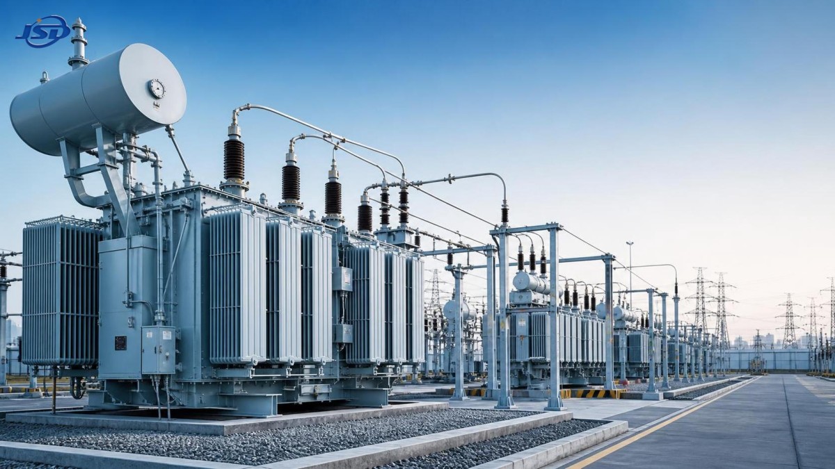
Thermal Design and Insulation Are Lifecycle Decisions
Transformer capacity is inseparable from thermal behavior. The winding hot-spot temperature, top-oil temperature, ambient conditions, cooling mode, and insulation system collectively influence how much load the unit can carry and how quickly its insulation ages. In many projects, the relevant challenge is not nominal load but repeated high-temperature operation during the periods when the network is least able to tolerate an outage.
Procurement specifications should clearly define the expected ambient temperature range, altitude, pollution level, solar exposure, ventilation conditions, and installation arrangement. Indoor transformer rooms, enclosed substations, coastal sites, desert installations, and high-altitude projects can impose very different constraints. A standard design may require derating or project-specific adaptation.
Cooling designation should be read as an operating assumption, not a label. Natural cooling has fewer moving components but provides less operational headroom. Forced-air or forced-oil cooling can increase capacity and improve loading flexibility, yet it introduces fans, pumps, controls, auxiliary power needs, and additional maintenance points. The decision should account for the consequences of cooling equipment failure and how alarms are integrated into the operator’s monitoring system.
Insulation selection should be tied to expected service life and loading duty. Decision-makers do not need to specify every material detail themselves, but they should require suppliers to explain the thermal design basis, permissible loading assumptions, and evidence supporting the proposed insulation system. A lower initial cost is not compelling if it relies on aggressive operating assumptions that leave little margin for summer peaks, contingency load, or delayed expansion.
Efficiency Should Be Measured in the Context of Actual Duty
Loss evaluation is frequently oversimplified. No-load losses occur whenever the transformer is energized, while load losses rise with the square of current. A transformer serving a lightly loaded but continuously energized network may place more economic emphasis on no-load loss. A heavily loaded industrial or urban transformer may justify close attention to load loss, conductor design, and cooling efficiency.
The appropriate comparison is lifecycle cost, not purchase price alone. That assessment should include expected loss energy over the operating profile, electricity valuation assumptions, capitalized loss methodology where applicable, maintenance requirements, outage exposure, and anticipated life. If a tender uses a loss capitalization formula, all bidders should be assessed against the same inputs; otherwise, a technically better design can appear more expensive simply because the comparison is inconsistent.
There is no universal “most efficient” utility transformer. The correct design depends on load factor, peak duration, operating voltage, and energy cost. Decision-makers should ask suppliers to state the guaranteed losses at the referenced conditions and explain whether quoted performance applies to the intended tap position and cooling state. Ambiguous loss data creates avoidable disputes after delivery.
Voltage Regulation, Impedance, and Protection Cannot Be Left Until Late Design
Voltage ratio and nominal power are only the beginning. Tap changer selection influences the transformer’s ability to maintain downstream voltage as load and supply conditions change. Off-circuit tap changers may be suitable for stable systems where adjustments are infrequent. On-load tap changers provide operational flexibility where voltage must be regulated under changing conditions, but they bring mechanical complexity and require a defined maintenance strategy.
Impedance is equally consequential. It affects fault current, voltage drop, parallel operation, and the performance of protection systems. Higher impedance may help limit fault levels, but it can worsen voltage regulation. Lower impedance can support voltage performance but may increase short-circuit duty on switchgear. This is a system tradeoff, not a transformer-only choice.
Before finalizing the specification, the project team should complete or update load-flow, short-circuit, protection coordination, and grounding studies. These studies should reflect likely expansion cases, not only the first day of operation. Retrofitting protection systems or replacing switchgear because fault duties were underestimated can erase the apparent savings of a low-cost transformer selection.
Digital monitoring also needs a practical business case. Winding-temperature indicators, oil-temperature monitoring, dissolved gas analysis interfaces, bushing monitoring, and remote communications can improve condition awareness, particularly for critical or difficult-to-access assets. However, data has value only if the organization has thresholds, responsibilities, and workflows for acting on it. A monitoring package that is not connected to maintenance decisions becomes an expensive reporting feature.
Expansion Planning Means Preserving Options, Not Buying Maximum Capacity
Overbuilding can tie up capital, increase no-load losses, and complicate installation. Underbuilding can force a disruptive replacement before the asset has delivered reasonable value. The more disciplined approach is to identify which expansion assumptions are sufficiently credible to influence today’s design and which should be accommodated through space, buswork, foundations, cable routes, and protection provisions instead of immediate transformer capacity.
For example, a substation may be designed for one transformer initially while reserving a second transformer bay, cable trench capacity, protection panels, and bus extensions for a future unit. This can be more economically rational than installing the ultimate capacity on day one, especially where load growth depends on uncertain tenant uptake or phased industrial investment.
Distributed energy resources can change the expansion calculation. Customer-side solar and storage may reduce daytime import but increase bidirectional power-flow requirements, change peak timing, or create new overnight charging demand. In residential and light-commercial settings, a compact solution such as the 51.2V Wall-mounted LiFePO4 Energy Storage Battery may help a customer shift limited local demand or support backup loads. Its role should not be confused with substation-scale capacity planning: a 5.12 kWh battery is a customer-side resource, and its practical impact depends on inverter settings, discharge duration, aggregation, and the coincidence of local peaks.
That distinction is increasingly important. Distributed storage can defer network reinforcement in certain locations, but only where the utility can reliably forecast, contract for, or control the resource during constrained periods. Planning credit should be based on verified availability and operating rules, not on installed battery nameplate totals.
Supplier Evaluation Should Test Execution Capability
Transformer procurement carries risks that are not visible in the technical data sheet. Manufacturing capacity, design control, material traceability, quality assurance, testing capability, transport planning, and field-service responsiveness all affect whether the equipment arrives on time and performs as specified.
Supplier evaluation should examine the proposed design and the manufacturer’s ability to execute it consistently. Useful questions include:
- What design standards and customer specifications govern the unit, and where are deviations documented?
- How are core steel, conductors, insulation materials, bushings, tap changers, and cooling equipment controlled and traced?
- Which routine, type, or special tests are included, and can the purchaser witness critical testing?
- How will the transformer be transported, stored, assembled, dried if necessary, and commissioned at site?
- What is the response path for defects, spare parts, technical support, and warranty claims?
- What lead-time assumptions depend on long-lead components, and what schedule risks remain?
Factory acceptance testing is an important checkpoint, but it is not the final assurance step. Site acceptance, oil handling, installation quality, torque control, protection testing, grounding, and commissioning records have a direct effect on early-life reliability. Responsibilities between manufacturer, EPC contractor, installer, and asset owner should be explicit before equipment reaches the site.
A Better Decision Framework
For a utility transformer purchase, the strongest decision is rarely the unit with the highest rating, the lowest quoted loss, or the lowest initial price. It is the design that remains defensible when demand peaks, ambient conditions rise, one network element fails, and the expansion forecast changes.
Decision-makers should require a short, comparable technical basis from each bidder: expected loading profile, contingency requirement, thermal margin, loss assumptions, tap and impedance rationale, standards compliance, test scope, delivery plan, and lifecycle cost view. Any major assumption that cannot be substantiated should be marked for review rather than buried in the bid comparison.
When those assumptions are made visible, transformer selection becomes less about buying a component and more about protecting the reliability and expansion options of the power system it serves.

Get a Quote
Regardless of whether you require general advice or specific support, we are happy to help you.
Send Us Your Inquiry Today

Jinshida Electric remains committed to contributing to global energy development through professional manufacturing and superior service.