





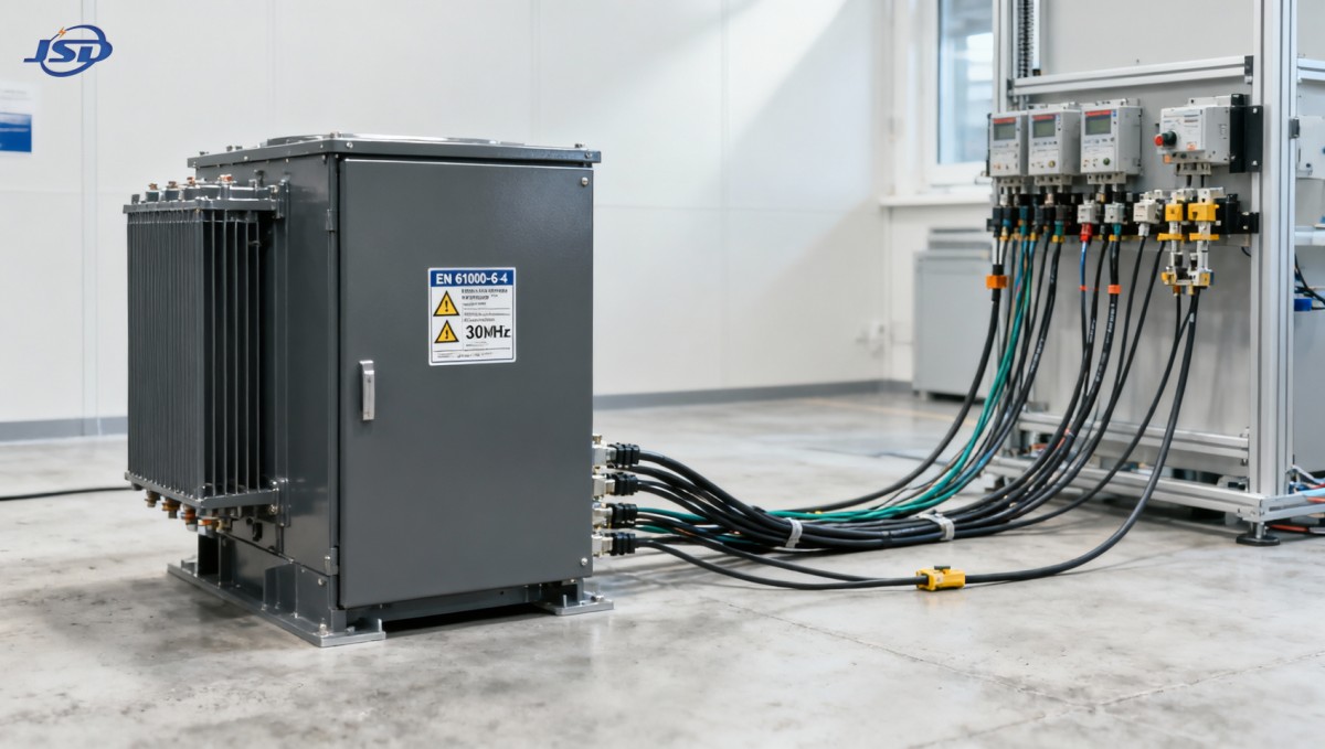
Do european compact substation transformer EMC compliance tests include conducted emissions up to 30MHz?
Yes—EMC compliance testing for a european compact substation transformer explicitly includes conducted emissions measurements up to 30 MHz. This is not optional, nor is it limited to certain configurations or voltage classes. It applies across the board to all low-voltage (LV) and medium-voltage (MV) auxiliary circuits, power supply ports, control wiring, and communication interfaces integrated into the unit.
Why 30 MHz Is the Hard Boundary—Not a Suggestion
The 30 MHz upper limit isn’t arbitrary. It reflects the physical and regulatory boundary between conducted and radiated emissions domains. Below 30 MHz, electromagnetic energy couples primarily through wires—power lines, signal cables, grounding conductors—and propagates as common-mode or differential-mode currents. Above 30 MHz, radiation dominates, and test methods shift to antenna-based far-field measurements in semi-anechoic chambers.
For a european compact substation transformer, this distinction matters because its enclosure integrates multiple subsystems: the transformer core/coils, LV switchgear, protection relays, SCADA interfaces, cooling controls, and often integrated metering. Each of these contributes noise at different frequencies—but only the sub-30 MHz range is assessed via conducted emissions tests. EN 61000-4-6 (immunity to conducted RF disturbances) and EN 61000-6-4 (emission limits for industrial environments) both define test setups and limits specifically for 150 kHz to 30 MHz. The lower bound (150 kHz) excludes audible harmonics and fundamental power-frequency disturbances; the upper bound (30 MHz) ensures compatibility with legacy control systems, PLCs, and protective relays still widely deployed in European grids.
What Ports Are Actually Tested—and Why It’s Not Just “the Input”
A common misconception among technical evaluators is that conducted emissions testing only targets the main HV/LV power terminals. In reality, EN 61000-6-4 requires testing on all accessible ports capable of coupling noise onto the grid or adjacent equipment. For a european compact substation transformer, that includes:
- Primary and secondary power supply ports (e.g., 35 kV input, 400 V output)—tested using Line Impedance Stabilization Networks (LISNs);
- Auxiliary AC/DC supply inputs (e.g., 230 V AC control power, 24 V DC for relays)—often overlooked but critical, as switching power supplies in control cabinets are major noise sources;
- Signal and communication ports (e.g., RS485, Modbus TCP gateways, IEC 61850 GOOSE links)—tested using coupling clamps or CDN adapters, especially when routed outside the enclosure;
- Grounding conductors—evaluated for common-mode current injection where grounding integrity affects noise return paths.
This holistic port coverage explains why design-level mitigation—not just post-build filtering—is essential. A transformer may pass emissions on its main LV bus but fail on a seemingly minor 24 V DC control feed if that line lacks proper ferrite suppression or PCB-level decoupling.
EN 50160 Is Not the EMC Standard—But It Shapes Real-World Expectations
While EN 50160 defines voltage characteristics (flicker, harmonics, dips, swells) at the point of common coupling, it does not specify EMC emission limits. However, it indirectly governs how strictly conducted emissions are enforced. Utilities across Germany, France, and the Nordics reference EN 50160 in grid connection agreements—and increasingly require full EN 61000-6-4 compliance as a prerequisite for energization. Why? Because uncontrolled sub-30 MHz noise from one compact substation can interfere with neighboring metering, fault recorders, or even wireless telemetry operating in the 1–30 MHz amateur or ISM bands.
This creates a practical reality: even if a european compact substation transformer meets the letter of EN 61000-6-4, it may face rejection during commissioning if field measurements show elevated noise on auxiliary circuits—especially where multiple units share grounding or cable trays. That’s why leading manufacturers like Jinshida Electric Power Technology Co., Ltd. validate not only lab-compliant LISN readings but also real-world coupling behavior during prototype integration testing.
Design-Level Mitigation: Where Testing Ends and Engineering Begins
Certified lab testing confirms compliance—but it doesn’t guarantee robustness in complex installations. Effective mitigation starts long before the test chamber:
- Filter placement: EMI filters must be mounted directly at port entry points—not inside the cabinet—otherwise internal wiring acts as an antenna;
- Grounding topology: Single-point grounding for control electronics avoids ground loops that amplify common-mode noise;
- Shielded cable routing: Signal cables running parallel to power feeds—even within the same conduit—induce coupling that no filter can fully suppress;
- Transformer winding layout: Interleaved HV-LV windings reduce capacitive coupling of high-frequency switching transients into LV circuits.
Jinshida Electric’s R&D team applies these principles across its portfolio—not just for utility-scale substations, but also for applications demanding rapid deployment in dynamic environments. For example, when integrating compact transformers with mobile power solutions like the 50kW/100kWh Portable Trailer Energy Storage System, attention to conducted emissions becomes even more critical. That system operates across construction sites and emergency rescue zones—environments with mixed grounding, temporary cabling, and proximity to sensitive comms gear—where noise from auxiliary transformer circuits could disrupt battery management (BMS) signals or EMS coordination.
When “Compliant” Isn’t Enough—The Role of Application Context
Technical evaluators should resist treating compliance as binary. Two units may both pass EN 61000-6-4—but one may operate 5 dB below the limit across 2–15 MHz (where many protection relays are most sensitive), while the other skirts the edge at 10 MHz and spikes at 25 MHz (near HF radio bands used for site coordination). The difference isn’t visible in the pass/fail report—it’s in the spectral plot.
Ask for full-frequency sweep data—not just margin reports. Check whether testing included worst-case load conditions (e.g., transformer energization, tap-changer operation, fan startup) and whether auxiliary circuits were powered and loaded during measurement. Also verify that the test lab was accredited to ISO/IEC 17025 for EN 61000-6-4:2019—some older certificates reference outdated 2007 or 2011 editions with looser limits.
Final Guidance for Technical Evaluators
If you’re assessing a european compact substation transformer for a project involving renewable integration, industrial automation, or distributed energy resources, here’s your actionable checklist:
- Confirm the test report cites EN 61000-6-4:2019 (or later), not earlier revisions;
- Verify conducted emissions were measured on all ports—not just primary power inputs;
- Request raw frequency-domain plots (not just tabulated margins) for auxiliary and control ports;
- Review grounding and shielding schematics—especially for signal interfaces exposed to external cabling;
- Assess whether the manufacturer provides application guidance for co-location with sensitive electronics (e.g., inverters, BMS, wireless gateways).
At Jinshida Electric Power Technology Co., Ltd., every european compact substation transformer undergoes this level of scrutiny—not to meet a checkbox, but to ensure predictable behavior where it matters most: at the interface between hardware, grid, and digital infrastructure. Because in modern energy systems, electromagnetic compatibility isn’t about passing a test. It’s about enabling reliable, interoperable operation—day after day, under real conditions.
Hot News
- 00
0000-00
How U.S. DOE efficiency rules affect distribution transformer manufacturers - 00
0000-00
How american type pad mounted transformer seismic qualification affects installation in California utility grids? - 00
0000-00
Do european compact substation transformer EMC compliance tests include conducted emissions up to 30MHz?
0000-00
Contact Us

Get a Quote
Regardless of whether you require general advice or specific support, we are happy to help you.
Send Us Your Inquiry Today

Jinshida Electric remains committed to contributing to global energy development through professional manufacturing and superior service.