





What Does a Main Power Transformer Do in a High-Voltage Substation?
What Does a Main Power Transformer Do in a High-Voltage Substation?
A main power transformer is the backbone of a high-voltage substation. Its central task is straightforward in principle: it changes electricity from one voltage level to another so power can travel efficiently across the grid and then be used safely by downstream networks, industries, transport systems, and communities.
In practice, however, a main power transformer does much more than “step voltage up or down.” It sits at a critical boundary between different parts of the electrical system. It affects how much power a substation can deliver, how stable the local voltage remains under load, how faults are managed, and how easily the network can be expanded later. When this transformer is unavailable, a large portion of the connected system may need to be transferred, curtailed, or taken out of service.
For anyone researching substation equipment, the useful question is not only what a transformer is, but what role it plays in the actual flow of power. The answer depends on whether the substation connects a generating station to the transmission network, transfers power between transmission voltage levels, or supplies a regional distribution system. The underlying electrical principle remains the same, while the design priorities can be very different.
The voltage bridge inside a substation
Electricity is transmitted at high voltage because higher voltage allows the same amount of power to move with lower current. Lower current generally reduces resistive losses in conductors and makes long-distance transmission more practical. Yet that transmission voltage is far too high for most end users and many local networks. A main power transformer creates the bridge between these levels.
At a transmission-to-distribution substation, for example, the transformer may receive power from a high-voltage line and reduce it to a medium-voltage level for outgoing feeders. Those feeders may then serve other substations, commercial zones, factories, renewable-energy connections, or urban distribution networks. In a generation facility, the direction is often reversed: a generator transformer raises voltage so generated power can enter the transmission system efficiently.
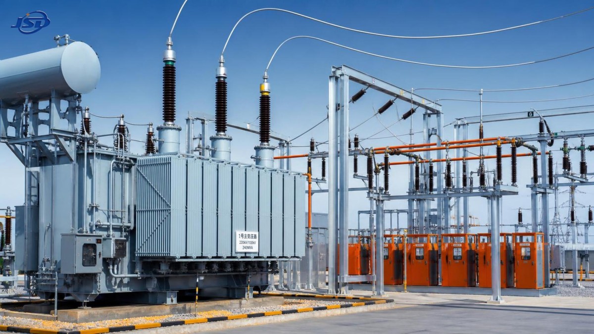
This is why the term main power transformer usually refers to more than a small auxiliary unit. It is commonly the highest-capacity transformer in the substation and one of the assets around which the station’s switchgear, protection arrangement, civil layout, cooling provisions, and maintenance strategy are planned.
How it changes voltage without changing frequency
A transformer works through electromagnetic induction. Alternating current in one winding produces a changing magnetic field in a laminated steel core. That changing field induces voltage in another winding. The relationship between the primary and secondary winding turns determines whether the voltage is raised or lowered.
The important point is that a conventional power transformer changes voltage but does not normally change frequency. A 50 Hz input remains 50 Hz at the output, and the same applies to a 60 Hz system. Frequency conversion requires power electronic equipment rather than a standard transformer alone.
There is no direct electrical connection between the windings in a typical two-winding transformer. Energy crosses through the magnetic field in the core. This separation provides useful electrical isolation, although it should not be confused with complete system protection. Earthing arrangement, insulation coordination, surge arresters, circuit breakers, relays, and operating procedures still determine how safely a substation responds to real faults and overvoltages.
More than voltage conversion: regulation, isolation, and grid behavior
A well-designed transformer helps a substation keep voltage within an acceptable operating range as demand changes. Load is rarely constant. Industrial motors start and stop, renewable generation fluctuates, and daily demand rises sharply in some networks. If voltage on the receiving side drifts too far, equipment performance and network reliability can suffer.
For that reason, many main transformers use tap changers. An on-load tap changer can adjust the transformer ratio while energized, allowing the substation to regulate secondary voltage without interrupting supply. This is a valuable capability, but it also adds mechanical complexity. In service experience, tap changer condition deserves close attention because it is a moving component operating within an otherwise largely static electrical machine. Maintenance planning should not focus only on the transformer tank and windings.
The transformer’s vector group is another practical issue. Winding connections and phase displacement affect how transformers can be paralleled, how zero-sequence currents behave during earth faults, and how harmonics are handled. A transformer that looks suitable based only on voltage and MVA rating may still be a poor fit if its vector group, neutral arrangement, or impedance does not match the surrounding system.
Impedance is especially easy to overlook in early discussions. It limits fault current to some degree, but it also causes voltage drop under load. Very low impedance is not automatically better; it can increase available short-circuit current and place additional duties on breakers and switchgear. Excessively high impedance may make voltage regulation more difficult. The appropriate balance has to be coordinated across the whole substation, not selected in isolation.
What determines the size and design of a main transformer?
Transformer selection starts with the network, not with a catalog rating. Engineers usually examine present demand, expected load growth, supply voltage, required outgoing voltage, power factor, redundancy philosophy, fault level, climate, installation location, and transport constraints. A transformer designed for a compact indoor city substation will face a different set of compromises from one installed outdoors at a remote renewable-energy collection point.
Cooling is a visible example. Oil-natural-air-natural cooling, commonly abbreviated ONAN, relies on natural circulation of insulating oil and ambient air. It is widely used and comparatively simple. Higher-capacity applications may require additional cooling stages using fans or pumps, depending on the specified thermal duty. The correct choice depends on loading profile, ambient conditions, site maintenance capability, and acceptable temperature rise. A unit can be electrically suitable on paper but operationally stressed if its cooling assumptions do not reflect the site.
Insulation level also needs careful coordination with the actual system voltage and expected surge environment. Lightning exposure, switching surges, cable connections, line length, and arrester placement all affect the insulation duty. This is one reason transformer procurement should include clear system information rather than only a request for “high voltage in, lower voltage out.”
For grid construction, industrial manufacturing, new-energy facilities, and infrastructure projects, reliable operation is usually the result of several connected decisions: sound electromagnetic design, appropriate materials, controlled manufacturing, correct test requirements, protection coordination, and installation discipline. Companies such as Jinshida Electric Power Technology Co., Ltd. approach power transmission and distribution equipment with this wider operating context in mind, rather than treating the transformer as a standalone box.
The transformer is part of a protection system, not a substitute for one
Because a main transformer represents a major concentration of energy, it is protected from both internal and external problems. Differential protection is commonly used to detect internal winding or core faults by comparing currents entering and leaving the protected zone. Other schemes may address overcurrent, earth faults, overfluxing, temperature, pressure changes, oil level, and cooling failure. The exact relay design depends on transformer construction and substation protection philosophy.
Protection settings must be coordinated carefully. A relay that trips too slowly can allow a fault to cause greater damage. One set too aggressively may disconnect healthy equipment during temporary disturbances. This is not a matter of simply adding more protection functions. It requires an understanding of transformer inrush current, through-fault capability, tap position effects, grounding method, and upstream and downstream breaker coordination.
Routine condition monitoring also matters. Operators often pay attention to oil condition, dissolved gas trends where applicable, winding and oil temperatures, bushing condition, cooling equipment, insulation resistance, and tap changer performance. Individual readings are less useful than trends interpreted alongside loading history and operating events. A sudden change after a fault, overload, or maintenance intervention deserves more scrutiny than a stable value observed over time.
Why industrial transformer duty can be different
Not every transformer connected to a high-voltage substation serves a conventional distribution load. Industrial processes such as electrolysis, electroplating, metallurgy, chemical processing, mining, rail transit, and power-electronic applications can produce highly demanding electrical conditions. Rectifier loads, for instance, may introduce harmonics, high currents, unusual load cycles, or stricter requirements for voltage stability and isolation.
In these cases, a main transformer may supply a dedicated process transformer rather than feeding ordinary distribution circuits directly. A specialized Isolation and Rectifier Special Transformer can provide voltage transformation and electrical isolation for rectifier equipment, while helping limit interference between the industrial load and the wider supply system. Available configurations may cover 50 kVA to 5000 kVA, high-voltage inputs such as 6 kV, 10 kV, 20 kV, or 35 kV, customized low-voltage outputs, and three-phase connections including Dyn11 or Yyn0. The right configuration still depends on the rectifier topology, harmonic study, earthing arrangement, and process duty.
Copper windings, suitable cooling, and insulation design are particularly relevant where duty is continuous or overloads are expected. IEC 60076 is a commonly referenced standard family for power transformers, but compliance with a general transformer standard does not by itself define every process-specific requirement. Projects involving rectifiers should make harmonic loading, temperature limits, short-circuit duty, and secondary voltage regulation explicit in the technical specification.
Common misunderstandings when evaluating substation transformers
One common misunderstanding is that transformer capacity should simply match the current connected load. In reality, planners may need to allow for future demand, emergency loading, loss of a parallel unit, and the practical cost of replacement or outage later. Oversizing without a reason is not ideal either, because capital cost and no-load losses must be considered. The sensible approach is to examine the load forecast and the network’s reliability requirements together.
Another mistake is treating nameplate voltage as the whole design question. Voltage ratio, rating, impedance, vector group, tap range, insulation level, cooling class, terminal arrangement, noise constraints, transport weight, and protection interfaces all affect whether the equipment will work smoothly at the site. These details become far more expensive to change once civil works, cable routes, and switchgear interfaces are fixed.
It is also worth separating reliability from the idea that a transformer should never require attention. Reliable equipment still needs inspection, testing, clean cooling paths, appropriate oil management where oil-filled designs are used, and records that make abnormal trends visible. A practical maintenance program is not an admission of weakness; it is part of how a long-life asset remains dependable.
A practical way to think about its role
The simplest description is that a main power transformer makes high-voltage power usable at the next stage of the network. The more complete description is that it sets the electrical relationship between two systems: voltage level, available capacity, fault behavior, grounding behavior, and, in many substations, the quality of voltage delivered to connected loads.
When evaluating one for a project, start with the single-line diagram and operating conditions rather than with a preferred transformer model. Confirm what the incoming system can deliver, what the outgoing system requires, how the station will operate during contingencies, and what loads may be added later. That process usually reveals whether the main concern is capacity, voltage regulation, harmonic duty, insulation coordination, redundancy, or site environment. A transformer is most reliable when its design reflects those real conditions from the beginning.

Get a Quote
Regardless of whether you require general advice or specific support, we are happy to help you.
Send Us Your Inquiry Today

Jinshida Electric remains committed to contributing to global energy development through professional manufacturing and superior service.