





Electrical Power Transformers Explained: Ratings, Components, and Uses
Electrical power transformers sit at the center of every modern power system, but they are often evaluated too late in a project. A transformer may appear to be a straightforward voltage-conversion device: power enters at one voltage level and leaves at another. In practice, its rating, insulation design, cooling method, impedance, tap range, connection arrangement, and installation environment can affect plant uptime, power quality, safety coordination, and lifetime operating cost.
For researchers, project engineers, and procurement teams, the useful question is rarely “What is a transformer?” It is “What must this transformer do in this particular electrical system, and what can go wrong if its operating conditions are misunderstood?” That distinction matters whether the project involves a utility substation, a manufacturing facility, a renewable-energy collection system, rail infrastructure, or a high-current rectifier installation.
Why transformers remain a critical system decision
Power is transmitted at high voltage because moving the same amount of energy at a higher voltage generally reduces current and associated line losses. Before electricity reaches industrial equipment, commercial buildings, transport systems, or residential loads, voltage must be stepped down to usable levels. Electrical power transformers make this process possible through electromagnetic induction, transferring energy between windings without a direct conductive connection between them.
That core function has not changed, but the conditions around it have. Loads are now more variable, electronic, and sensitive. Renewable generation can introduce changing power flow and voltage conditions. Industrial facilities increasingly use variable-frequency drives, furnaces, electrolysis systems, chargers, and other power-electronic loads that create harmonics. In these settings, selecting equipment simply by nominal kVA and primary voltage can produce an installation that works on day one but runs hotter, trips more often, or ages faster than expected.
A transformer should therefore be treated as part of a power system rather than an isolated purchase. Its design needs to align with the upstream supply, downstream loads, protection scheme, earthing arrangement, expected duty cycle, and physical site conditions.
The ratings that deserve attention
The nameplate is the starting point, not the full answer. Several ratings need to be read together because each describes a different operational limit or system behavior.
Capacity is frequently oversimplified. A 1,000 kVA transformer is not necessarily the right choice for a load calculated at 1,000 kVA. The load may be continuous, seasonal, intermittent, nonlinear, or subject to motor-starting peaks. The site may be hot, poorly ventilated, at altitude, or exposed to solar gain. These factors influence winding temperature and insulation aging. A sensible specification establishes the real load profile before choosing a margin; blindly oversizing can raise capital cost, no-load losses, and footprint without solving the underlying issue.
Voltage ratio also requires more than a nominal match. A facility supplied at 10 kV, for example, may experience normal operating variation, while the downstream process may require a tightly controlled voltage. Tap changers, either off-circuit or on-load depending on the application, can help maintain an acceptable secondary voltage. The required regulation range should be established alongside the utility supply characteristics, rather than added as an afterthought.
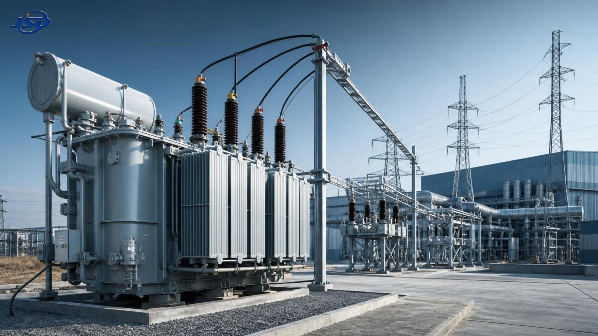
What is inside a power transformer
Most transformer performance and reliability decisions trace back to a small number of physical elements. The magnetic core provides a low-loss path for magnetic flux. It is typically assembled from laminated electrical steel to limit eddy-current losses. The windings, generally made from copper or aluminum conductors depending on the design and application, create the primary and secondary electrical circuits.
Insulation separates winding turns, winding sections, and live parts from grounded structures. In liquid-filled equipment, insulating oil can provide both dielectric strength and heat transfer. The tank, radiators, conservator arrangement where used, bushings, pressure-relief devices, oil-level indicators, and temperature-monitoring equipment all support safe operation. Dry-type units use air, resin, or solid insulation systems rather than insulating liquid, which changes their installation and maintenance considerations.
Buyers often focus on visible accessories but overlook the relationship between core-and-coil design, insulation class, loss performance, and thermal capability. A transformer’s external dimensions may look similar across suppliers while internal conductor sizing, cooling ducts, insulation margins, clamping arrangements, and test discipline differ materially. For critical service, a technical comparison should go beyond the quotation headline.
Losses are not only an efficiency figure
Transformer losses are commonly divided into no-load loss and load loss. No-load loss occurs whenever the transformer is energized, even with little or no secondary load. Load loss rises with current and includes winding resistance and additional stray losses. Their relative importance depends on operating hours and loading profile.
For a continuously energized distribution asset, no-load loss can be commercially significant over its service life. For a heavily loaded industrial unit, load loss and temperature rise may deserve greater attention. The lowest purchase price may therefore not represent the lowest total cost. A valid lifecycle comparison should use the project’s expected energy cost, annual operating hours, loading curve, and reasonably stated loss data. When those inputs are uncertain, the savings estimate should be treated as provisional rather than presented as a guaranteed result.
Different applications create different transformer requirements
Utility and distribution transformers are generally selected around network voltage, load density, fault level, regulation requirements, outdoor exposure, and maintainability. Industrial transformers must also accommodate the character of the plant load. A transformer serving a steady group of conventional motors faces a different duty from one supplying a rolling mill, arc furnace, data center, large drive system, or battery-production line.
Renewable-energy projects introduce another layer of assessment. Wind and solar installations may require collector-system transformers exposed to changing generation, voltage rise, remote locations, and demanding transport constraints. The transformer is only one part of the project’s electrical design, but its impedance, vector group, tap arrangement, insulation coordination, and monitoring strategy can affect the entire collection network.
Rail, mining, chemical processing, electroplating, and metallurgy frequently involve rectifier-fed processes. These loads can impose high current, harmonic content, rapid load changes, or a need for electrical separation between the supply and process equipment. In such cases, a general-purpose distribution transformer may not be sufficient. A purpose-designed Isolation and Rectifier Special Transformer can be considered where isolation, voltage transformation, and stable supply for industrial rectifier systems must be addressed together. Its suitability still depends on the actual harmonic spectrum, required pulse configuration, duty cycle, cooling conditions, and protection design.
This is an area where “higher capacity” is not automatically a substitute for the correct design. Harmonic currents increase losses in windings and structural parts, while rectifier duty can create electrical and thermal stresses not represented by a simple balanced sinusoidal load calculation. The supplier should be given the rectifier topology, expected current waveform where available, operating cycle, overload requirement, and upstream system conditions.
Oil-filled versus dry-type: the decision is contextual
Oil-filled transformers are widely used in utility and industrial applications because liquid insulation and cooling can support high ratings in compact designs. They may be well suited to outdoor substations, larger capacities, and applications where established oil monitoring and maintenance practices are available. Their use, however, requires attention to fire protection, spill containment, environmental rules, and access for inspection or oil testing.
Dry-type transformers are often selected for indoor locations where liquid containment or fire-risk considerations are important, such as commercial buildings, certain public facilities, and some industrial spaces. They can reduce concerns associated with insulating liquid, but they are not maintenance-free and are not universally preferable. Ventilation, dust accumulation, humidity, thermal cycling, and acoustic performance still need evaluation. In harsh industrial areas, contamination and restricted airflow can materially affect service life.
The right choice follows the installation risk assessment. Site fire strategy, available space, ambient conditions, capacity requirement, maintenance capability, and local codes all matter. A dry-type unit should not be selected solely because it is described as safer, nor should an oil-filled unit be ruled out without considering the engineering controls available at the site.
Questions that improve a procurement specification
A strong request for quotation gives manufacturers enough system context to design and price responsibly. It also makes technical offers more comparable. At a minimum, the purchaser should clarify:
- Primary and secondary voltage, system frequency, phase arrangement, and neutral grounding method.
- Required capacity, actual load profile, future expansion expectation, and permitted overload duty.
- Whether the load includes drives, furnaces, rectifiers, chargers, UPS systems, or other nonlinear equipment.
- Required vector group, impedance range, tap configuration, and parallel-operation requirements.
- Installation location, indoor or outdoor use, altitude, minimum and maximum ambient temperature, humidity, dust, corrosive atmosphere, seismic exposure, and available ventilation.
- Preferred cooling method, enclosure or tank requirements, cable-entry arrangement, and space or transport constraints.
- Applicable project standards, utility requirements, inspection expectations, factory acceptance tests, and documentation needs.
IEC 60076 is a widely referenced family of standards for power transformers, but citing the standard alone does not complete a specification. The relevant parts, contractual test requirements, site regulations, and any customer-specific technical conditions should be confirmed for the project. Certification and compliance claims should be checked against the supplied documentation and the jurisdiction where the transformer will operate.
Reliability depends on operation after delivery
Transformers have long service lives when their thermal, electrical, and environmental limits are respected. Many failures are not caused by a single dramatic event. They develop through moisture ingress, overloaded operation, inadequate ventilation, loose connections, contaminated insulation, cooling-system defects, repeated fault stress, or unrecognized harmonic loading.
Commissioning is a particularly important control point. Teams should verify the nameplate against the approved design, confirm the vector group and phase relationship, inspect grounding and terminations, test insulation as required, confirm protective settings, and ensure that cooling and monitoring devices operate correctly. For oil-filled units, baseline records for oil condition and key electrical tests can make later condition assessment more meaningful.
Condition-based maintenance becomes increasingly valuable as asset criticality rises. Typical methods may include visual inspection, temperature trending, thermography, oil analysis where applicable, dissolved gas analysis for suitable liquid-filled equipment, insulation testing, and review of loading data. No single test provides a complete diagnosis. Trends, operating history, and the known construction of the transformer should be interpreted together.
A practical way to assess the next step
For early-stage research, begin by identifying the electrical role: grid step-up, distribution step-down, isolation, process supply, renewable collection, or rectifier duty. Then define the operating environment and load behavior before narrowing the design. This order prevents a common error: choosing a familiar transformer category first and attempting to force it into a duty it was not designed to handle.
The most useful supplier discussion is built around system data, not just a target price and kVA figure. When technical teams can compare loss values, temperature-rise limits, impedance, winding material, cooling design, test scope, delivery constraints, and service support on the same basis, the decision becomes more defensible. In the transformer sector, reliable power delivery is rarely the result of one headline specification. It comes from matching the equipment to the network, the load, and the conditions it will face for years after installation.

Get a Quote
Regardless of whether you require general advice or specific support, we are happy to help you.
Send Us Your Inquiry Today

Jinshida Electric remains committed to contributing to global energy development through professional manufacturing and superior service.