





Why Amorphous Alloy Cores Deliver Lower No-Load Loss Than Silicon Steel
A low loss amorphous alloy transformer reduces no-load loss primarily because its core material requires less energy to reverse magnetic direction during every alternating-current cycle. The difference begins at the atomic level. Silicon steel has an ordered crystalline structure, while amorphous alloy is rapidly solidified into a thin ribbon before crystals can form. Its atoms remain in a disordered arrangement, which gives the material a much lower resistance to repeated magnetization and demagnetization.
No-load loss exists whenever a transformer is energized, even when its secondary side supplies little or no load. It is therefore governed mainly by the core, applied voltage, frequency, magnetic flux density, material condition, and core assembly quality. Winding resistance has little influence on this loss category. A comparison between amorphous alloy and silicon steel must consequently focus on magnetic behavior rather than rated output alone.
Magnetic domain movement requires less energy
Ferromagnetic materials contain magnetic domains: small regions whose magnetic moments are aligned internally. When alternating voltage is applied to a transformer winding, the core flux changes direction each half-cycle. Domain walls move and domain orientations rotate in response. Energy expended in this repeated process becomes hysteresis loss.
Grain-oriented silicon steel is designed to guide magnetic flux efficiently along its rolling direction. It remains an effective transformer-core material, especially where mechanical strength, established processing methods, and compact core geometry are important. Yet its crystalline grains, grain boundaries, and crystal anisotropy create barriers to domain movement. Reversing magnetization requires a measurable magnetic field, represented by the area enclosed by the material's hysteresis loop.
Amorphous alloy has no long-range crystal lattice and no conventional grain boundaries. The absence of regular crystal structure reduces magnetocrystalline anisotropy, so the magnetic domains encounter fewer fixed structural obstacles as they reorient. Its hysteresis loop is correspondingly narrow. Less loop area means less energy dissipated per magnetization cycle, directly lowering the hysteresis component of no-load loss.
This material property is particularly significant because a distribution transformer may remain energized for most of its service life. Load loss rises and falls with current, whereas core loss persists whenever rated voltage is present. A modest reduction in continuously occurring loss can therefore be operationally meaningful over long energized periods.
Thin ribbons suppress circulating eddy currents
Core loss also includes eddy-current loss. Changing flux induces voltages within the conductive core material itself. Those voltages drive local circulating currents, and their resistive heating consumes energy. Eddy-current loss is strongly influenced by lamination thickness, electrical resistivity, frequency, and flux density.
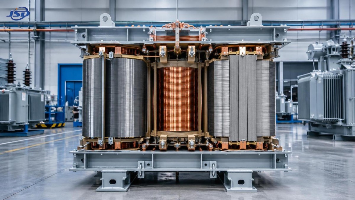
Silicon steel cores are assembled from insulated laminations to interrupt these current paths. The approach is effective, but the individual sheets are substantially thicker than amorphous metal ribbon. Amorphous alloy is commonly manufactured as very thin strip, then coated with an insulating layer and wound into a core. The short dimension across the ribbon sharply limits the area available for induced current loops.
The amorphous alloy composition also has comparatively high electrical resistivity. Combined with ribbon thickness, that property lowers the eddy-current component without relying solely on interlaminar insulation. The result is a material-level advantage rather than an improvement created only by changing a transformer’s external configuration.
Neither effect should be viewed in isolation. A low hysteresis material can still incur unnecessary eddy-current loss if ribbon insulation is damaged or conductive bridges are introduced during core assembly. Conversely, thin laminations alone do not produce the low hysteresis behavior associated with amorphous metal. The reduced no-load loss comes from the combination of low coercive behavior, high resistivity, and very thin insulated ribbon.
Flux density changes the comparison
Amorphous alloy is not normally selected by simply replacing silicon steel with an equal mass of material. Its saturation flux density is lower than that of common electrical steel grades. To avoid approaching saturation at rated voltage, the transformer design often uses a larger effective core cross-section or operates at a lower flux density. That geometry affects core window allocation, winding dimensions, tank arrangement, sound behavior, and total mass.
This is a frequent source of misleading comparisons. A smaller silicon-steel core and a larger amorphous core may have the same rated power, but their flux densities, excitation currents, and manufacturing constraints can differ. Comparing loss values only against transformer kVA rating obscures the actual design basis. The relevant comparison is between complete transformers tested under the same voltage waveform, frequency, tap position, temperature condition, and applicable test method.
Voltage sensitivity also deserves attention. Core flux is approximately proportional to applied voltage divided by frequency. Sustained overvoltage, low-frequency operation, or harmonic voltage distortion can increase peak flux and raise excitation loss. Since amorphous designs are often optimized around a controlled nominal flux density, site voltage conditions should be considered rather than assumed to be ideal.
Harmonics do not affect every loss mechanism in the same way. Higher-frequency flux components tend to increase eddy-current effects, while waveform peaks can push local portions of the core closer to saturation. A low fundamental-frequency no-load loss result does not automatically predict behavior under a highly distorted supply. The transformer’s published no-load loss test point remains valid, but it should not be treated as a universal representation of every waveform.
Core construction can preserve or erode the material advantage
Amorphous ribbon is thinner and more mechanically sensitive than conventional silicon-steel laminations. Manufacturing details therefore have an unusually direct connection to final performance. Bending, punching, excessive clamping pressure, localized stress, and rough handling can introduce magnetically unfavorable stress states. Those stresses impede domain movement and increase core loss or magnetostriction-related noise.
Many amorphous transformer cores use wound or cut-core arrangements because the ribbon cannot be processed like standard stamped laminations without penalty. After cutting and forming, the core may require controlled heat treatment to relieve internal stress and establish the intended magnetic characteristics. Core joints must then be assembled with accurate overlap and consistent closure. A poorly closed joint raises local reluctance, increases magnetizing current, and can create localized flux concentration.
Transport and installation are also relevant. Mechanical shock, loose clamping structures, or excessive vibration can alter core stress distribution. These issues do not necessarily create an immediate electrical failure, but they can shift audible sound or no-load current away from expected values. When an unexpectedly high no-load loss result appears, the investigation should distinguish between test-system error, voltage waveform effects, core-joint condition, winding-related excitation problems, and mechanical stress introduced after manufacture.
Loss figures need a common test basis
No-load loss is measured with rated voltage applied to one winding while the other winding is open. The measured input power includes core loss and a small amount of winding loss caused by excitation current. Because excitation current is relatively low, the core dominates, but the test setup still matters. Voltage should be regulated, waveform distortion controlled, and measurement equipment suitable for low power-factor conditions.
Test reports should clearly identify rated voltage, frequency, energized winding, tap position, measured no-load current, and the temperature or correction convention used. Values without this context are difficult to compare. A transformer designed for one frequency should not be judged against a loss figure obtained at another frequency, and a measurement at reduced voltage cannot substitute for a rated-voltage no-load loss result.
Lower no-load loss does not eliminate design tradeoffs
Amorphous alloy is most compelling where the transformer remains energized for long intervals and average loading does not dominate total energy loss. A continuously energized unit serving intermittent demand has substantial hours during which core loss represents a large share of its energy use. Where loading is consistently high, winding loss, conductor size, cooling arrangement, and impedance may carry greater weight in the overall efficiency calculation.
Sound must also be evaluated separately from no-load loss. Magnetostriction causes dimensional changes as magnetic flux varies, producing vibration that can be transmitted through the core, clamping system, tank, and mounting structure. Material selection influences this behavior, but sound level also depends on core geometry, assembly force, resonance, and the installation environment. Two transformers with similar core loss values can produce different acoustic results.
For renewable-energy and grid-side installations, transformer selection should also account for the operating profile of connected equipment. A containerized storage installation such as the 1MW/2MWh Liquid Cooling Container Energy Storage System can impose changing charge and discharge currents, while the associated transformer may remain energized between dispatch events. The core-loss benefit is assessed from that energized duration, whereas copper loss must be assessed from the actual current profile and harmonic content of the power-conversion system.
Reading a specification without overstating the result
A low no-load loss value is meaningful only when it belongs to a complete and compatible design. Core material alone does not establish transformer performance. The same amorphous alloy can yield different results when core cross-section, joint pattern, annealing process, flux density, winding design, and clamping method change. Similarly, a silicon-steel transformer can be well engineered and appropriate where physical size, sound restrictions, overload duty, or existing installation constraints govern the design.
The defensible technical conclusion is narrower: amorphous alloy cores have an inherent material advantage for no-load loss because their non-crystalline structure reduces hysteresis loss and their thin, high-resistivity ribbons restrict eddy currents. That advantage is retained only when the transformer is designed around the material’s lower saturation flux density and when manufacturing, testing, transport, and installation avoid introducing stress or measurement bias that masks the intended performance.

Get a Quote
Regardless of whether you require general advice or specific support, we are happy to help you.
Send Us Your Inquiry Today

Jinshida Electric remains committed to contributing to global energy development through professional manufacturing and superior service.