





Which factory tests matter for an open type diesel generator?
Which Factory Tests Matter for an Open Type Diesel Generator?
For quality-control and safety teams, factory testing is the first line of defense against costly generator failures and operational risks. A qualified open type diesel generator manufacturer should verify performance, protection functions, electrical output, and load capability before delivery. This guide explains which factory tests matter most, helping buyers assess generator reliability, compliance, and suitability for demanding industrial and infrastructure applications.
An open type diesel generator is not simply an engine coupled to an alternator. It is an integrated power system comprising the diesel engine, alternator, controller, circuit breaker, fuel and cooling arrangements, battery-starting system, frame, wiring, and protective devices. A weakness in any one of these parts can affect the complete package. This is particularly relevant where the generator feeds a transformer, automatic transfer switch, motor loads, distribution board, or temporary site network.
The right factory acceptance test (FAT) should therefore answer practical questions: Can the unit start when required? Does it maintain voltage and frequency under changing load? Will it trip safely for real faults rather than nuisance alarms? Is the installed alternator suitable for transformer inrush and other reactive loads? And are the results traceable to the actual serial-numbered machine being delivered?
Start with the test basis, not a generic checklist
Before witnessing any test, the buyer should confirm the agreed rating and operating duty. Standby, prime, and continuous ratings are not interchangeable. Load acceptance, permitted overload, maintenance intervals, and temperature conditions may differ depending on the rating definition and the project specification. ISO 8528 is widely referenced for generating sets, but the exact applicable parts, site requirements, and local electrical rules should be identified in the contract rather than assumed.
The test record should state at least the generator model, engine and alternator serial numbers, rated kW/kVA, power factor, voltage, frequency, ambient conditions where measured, controller configuration, and calibration status of the test instruments. A performance report without unit identification has limited value: it may prove that a similar machine was tested, not that the shipped machine passed.
For projects involving transformers, the specification should also define the voltage arrangement, earthing philosophy, neutral treatment, transformer vector group where relevant, and whether the generator will start transformer-connected loads directly. These details influence alternator sizing, voltage regulator behavior, breaker settings, and the meaningfulness of the FAT.
Visual, mechanical, and wiring inspections catch basic but serious faults
A visual inspection may sound elementary, yet it often reveals problems that cannot be corrected by a good load-bank graph. Quality teams should examine the nameplates, rating labels, lifting points, baseframe welds, anti-vibration mounts, guards around rotating parts, exhaust insulation or shielding where supplied, fuel-line routing, hose clamps, battery restraint, and accessible emergency-stop devices.
An open generator has exposed components by design, so safe access and protection against accidental contact require close attention. Check that cable terminals are enclosed as specified, grounding points are clearly marked, control-panel doors close correctly, and power wiring is routed away from hot exhaust sections and moving parts. Loose ferrules, inconsistent wire numbering, missing gland plates, and poor cable support are not cosmetic defects. Vibration and thermal cycling can turn them into intermittent faults after installation.
Mechanical checks should also include engine oil, coolant, fuel level or fuel-system readiness for the test, belt condition, fan clearance, radiator integrity, and signs of leakage during and after operation. For a skid-mounted unit, verify that the baseframe has no distortion and that transport restraints, if provided, do not compromise normal vibration isolation.
Electrical safety tests: insulation, continuity, and phase verification
Electrical tests should be performed with an understood procedure and safe isolation. Insulation resistance testing is a core check for alternator windings, output circuits, and relevant control wiring. The test voltage, acceptance criterion, winding temperature, and equipment disconnected for the test all matter. A raw insulation-resistance value is not meaningful if the method is unclear or if sensitive electronic equipment was left connected.
Protective-earth continuity should be checked between exposed conductive parts, the generator frame, panel earth bar, and designated earthing terminals. This does not replace site earthing design, but it confirms that the factory-built assembly has a continuous protective path. Phase sequence should be verified at the output terminals, especially when the generator is intended to connect with transformer-fed distribution equipment or parallel-capable systems. A reversed phase sequence can cause motor rotation errors and commissioning delays.
The factory should also confirm rated output voltage and frequency at no load. For a three-phase generator, measure phase-to-phase and phase-to-neutral voltage where a neutral is available. Significant imbalance at no load deserves investigation before the unit is accepted, even if it appears to run smoothly.
Load-bank testing is the central proof of generator performance
The most useful FAT is a controlled load test using a suitable load bank. It demonstrates that the engine governor, automatic voltage regulator (AVR), alternator, cooling system, breaker, and controller operate together under demand. No-load running alone cannot expose inadequate fuel delivery, overheating, unstable governing, weak voltage regulation, or a circuit breaker that trips prematurely.
A normal test plan commonly includes several load steps, such as 25%, 50%, 75%, and 100% of the contracted rating, held long enough to observe stable values. The exact duration should follow the purchase specification, the rating basis, and the manufacturer’s approved procedure. During each step, record voltage, frequency, current per phase, kW, kVA, power factor where available, oil pressure, coolant temperature, battery-charging condition, and abnormal smoke, noise, vibration, or leakage.
The key question is not whether every displayed value is perfectly fixed. A diesel engine responds dynamically. What matters is whether voltage and frequency remain within the tolerances agreed for the set and whether the unit stabilizes predictably after load changes. Sudden load application and rejection tests are especially revealing because they show the response of the governor and AVR. Review the recorded transient behavior rather than relying only on a technician’s statement that the response was “normal.”
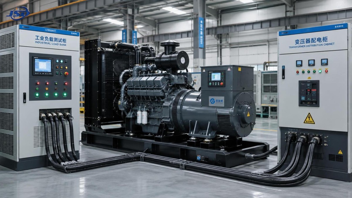
Resistive load banks are practical and widely used, but they do not fully reproduce the behavior of large motors, rectifiers, UPS systems, or transformer energization. If the installation will energize a transformer from the generator, inrush current can create a short-duration voltage dip well beyond the demand represented by steady resistive loading. The design review should consider alternator subtransient reactance, AVR forcing capability, generator impedance, transformer size, and the intended switching sequence. That assessment may be as important as the routine FAT.
Protection testing must verify both trip logic and safe shutdown
A generator that produces acceptable electrical output but ignores a genuine fault is not ready for service. Protection-function testing should cover the devices fitted to the supplied set and the project’s control philosophy. Typical functions include emergency stop, overspeed shutdown, low oil-pressure alarm or trip, high coolant-temperature alarm or trip, low and high battery voltage indication, failure-to-start logic, overcurrent protection, and abnormal voltage or frequency alarms.
Not every protection should be tested by physically creating a destructive condition. Many can be verified through controller simulation, sensor substitution, test inputs, or approved functional procedures. The purpose is to demonstrate the complete sequence: detection, alarm, breaker action where applicable, engine shutdown or cooldown, fault indication, and reset behavior. Witnesses should note whether each alarm is latched, whether it is logged by the controller, and whether the cause remains identifiable after a power cycle.
Breaker testing deserves more than opening and closing the device. Confirm its rated frame and trip settings against the design documents, verify local and remote commands if provided, and check interlocks. Where an automatic transfer switch or synchronizing panel is outside the generator scope, the interface signals should still be checked point by point. Many commissioning issues arise at these boundaries: two systems may be individually functional but use incompatible dry contacts, start logic, or neutral arrangements.
Starting, control, and communications tests reflect real operating conditions
A cold-start demonstration is more useful than observing a generator that has already been warmed up for testing. The unit should show reliable crank, start, oil-pressure build-up, stable idle-to-rated-speed transition, and battery charging. If preheaters, jacket-water heaters, fuel heaters, or automatic exercise functions are included, their operation should be documented. The actual site climate may require additional assessment; a factory run in mild conditions cannot by itself confirm winter performance.
Control tests should include local manual start/stop, automatic start input, remote-stop behavior, emergency stop, and alarm reset. For monitored facilities, validate the required communication interface and data points. A Modbus connection that merely establishes communication is not enough; the project team needs to confirm the registers, status definitions, alarm mapping, and time synchronization needed by the supervisory system.
This matters when generators are part of hybrid temporary-power arrangements. A trailer-mounted battery system can reduce abrupt diesel loading, support quieter periods, and provide a controlled power bridge during deployment. For example, the 100kW/215kWh Mobile Trailer Energy Storage System is designed for grid, solar PV, and diesel-generator charging, with a 100 kW PCS, 400 V AC output, LiFePO4 batteries, BMS and EMS control, and support for parallel operation. In such an arrangement, factory review should extend to generator charging limits, frequency and voltage acceptance windows, communication logic, and fault response between the two systems. A generator FAT cannot validate the complete hybrid plant unless those interfaces are included in the agreed scope.
What a useful FAT dossier should contain
The final documentation is part of the deliverable, not an afterthought. A robust dossier normally includes the approved data sheet, general arrangement drawing, wiring diagram, bill of major components, nameplate details, inspection checklist, test report, instrument identification, controller configuration or settings record, and manuals. Any deviations, rework, failed test, or retest should be visible in the record rather than removed from it.
It is also wise to distinguish factory verification from site acceptance testing. The FAT confirms workmanship and performance under factory conditions. Site acceptance should confirm installation-specific matters: ventilation, exhaust routing, fuel storage, foundation or trailer positioning, earthing, cable sizing, transformer interface, ATS operation, real connected loads, and local safety requirements. Passing one does not eliminate the need for the other.
Assess the manufacturer’s testing discipline, not just the pass result
When evaluating an open type diesel generator manufacturer, quality teams should look for repeatable control of the whole process: incoming inspection of critical components, assembly checks, calibrated test equipment, documented corrective action, traceability, and technicians who can explain the results. A rushed test with incomplete readings may be more concerning than a minor issue found and corrected transparently.
For power projects that combine generators, transformers, distribution equipment, and emerging energy-storage assets, the most reliable suppliers treat interfaces as engineering responsibilities rather than commercial exclusions. Jinshida Electric Power Technology Co., Ltd. applies this perspective through its work in power transmission and distribution equipment, supported by technical teams, advanced manufacturing processes, and rigorous quality management. Stable power support depends not only on the performance of individual equipment, but also on how protection, voltage compatibility, monitoring, and operating sequences are verified together.
Before release for shipment, ask for the approved FAT procedure in advance, identify the tests that must be witnessed, and align the test scope with the actual downstream loads. For a generator feeding a transformer or a hybrid energy system, the most valuable question is not simply “Did it reach rated power?” It is whether the tested machine, with its documented settings and interfaces, can behave safely and predictably in the power system it was purchased to support.

Get a Quote
Regardless of whether you require general advice or specific support, we are happy to help you.
Send Us Your Inquiry Today

Jinshida Electric remains committed to contributing to global energy development through professional manufacturing and superior service.