





When does a 2000 kVA transformer become undersized after load growth?
A 2000 kVA transformer becomes undersized when its real operating duty no longer leaves a dependable thermal, voltage, and expansion margin. The nameplate may still say 2000 kVA, and the unit may still be running, but that does not mean it remains suitable for the changed load. Repeated high loading, poor power quality, elevated ambient temperature, or a new concentration of motor and converter loads can turn an apparently adequate transformer into the weak point of the distribution system.
The practical question is not simply, “Has the transformer reached 2,000 kVA?” It is: “Can it carry the actual peak duty, under the actual site conditions, without unacceptable temperature rise, voltage drop, insulation aging, or loss of contingency?” A sound answer needs measured data, not a single monthly utility bill.
In many facilities, the warning appears after an expansion project: extra production lines are added, a new HVAC plant starts, chargers or variable-speed drives are installed, or the operating schedule changes from one shift to continuous operation. The transformer does not usually fail on the first busy day. It begins accumulating heat and insulation stress over time.
When a 2000 kVA transformer is no longer large enough
There is no universal percentage at which every 2000 kVA transformer becomes undersized. Transformer loading capability depends on its design, cooling arrangement, insulation thermal class, temperature-rise rating, ambient conditions, installation environment, harmonic content, and the duration of the load. The manufacturer’s loading guide and applicable standards should always take priority over a generic rule of thumb.
Still, an installed transformer should be treated as capacity-constrained when one or more of these conditions becomes persistent:
- Recorded maximum demand approaches the rated kVA during normal production, rather than during a rare short event.
- Peak loading lasts for several hours, especially in hot weather or in a poorly ventilated transformer room.
- Oil or winding temperature indicators trend upward after a load increase and no longer return to their normal range between peaks.
- Low-voltage bus voltage falls noticeably when large motors, welders, crushers, pumps, or process equipment start.
- Protection devices, cable terminations, busbars, or panel components show repeated heat-related alarms or abnormal temperatures.
- The next approved expansion would require routine operation close to the transformer’s nameplate rating.
A transformer can tolerate certain overload conditions if they are evaluated correctly. That is different from designing a site around overload operation. Short-duration peaks after a long low-load period may be acceptable; a daily flat load near the thermal limit is a different case entirely. The latter gives the transformer little opportunity to cool and accelerates insulation aging.
Direct answer: a 2000 kVA unit is undersized when the expected load profile and site conditions require it to operate with too little thermal and voltage margin, even if the measured peak has not yet exceeded 2,000 kVA. Persistent loading, heat, harmonics, and planned growth matter more than the nameplate number alone.
Start with kVA, not only kW
A common assessment error is comparing the transformer rating directly with plant kW demand. Transformers are rated in kVA because they supply both real power and reactive power. The basic relationship is:
kVA = kW / power factor
For example, a site drawing 1,500 kW at a 0.90 power factor requires approximately 1,667 kVA. At a 0.80 power factor, the same 1,500 kW requires 1,875 kVA. The production output has not changed, but the burden on the transformer has increased materially.
That calculation is useful, but it is only the starting point. A logged kW maximum does not always reveal the true kVA peak, particularly where capacitor banks switch poorly, loads vary quickly, or the meter does not capture sufficient interval detail. Use interval data that is short enough to show meaningful peaks. For fast-changing industrial processes, supplemental power-quality monitoring may be necessary.
Three-phase current provides a second check:
kVA = √3 × line voltage × line current / 1,000
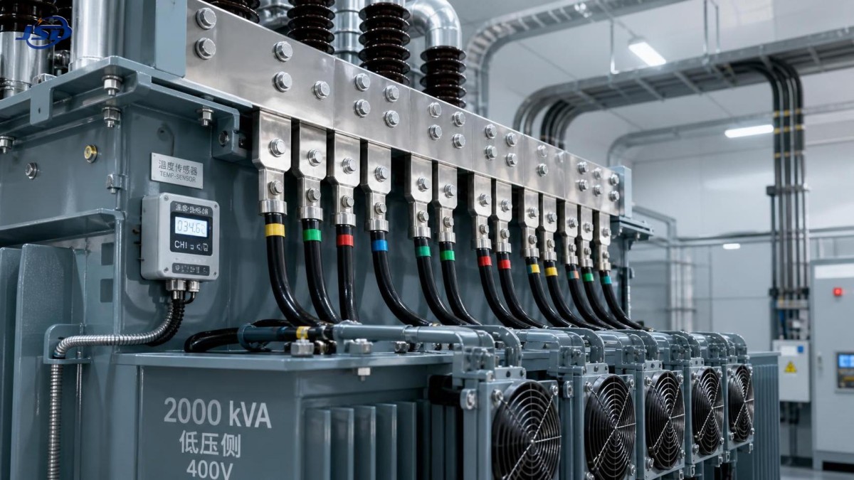
At 400 V, a 2,000 kVA transformer has a full-load secondary current of roughly 2,887 A. At 415 V, it is roughly 2,782 A. These figures help confirm whether low-voltage switchgear, bus ducts, cables, and feeder breakers remain adequate as well. Replacing only the transformer while leaving an undersized downstream path is a costly partial solution.
The loads that make the nameplate misleading
Not all kVA is equally easy for a transformer to supply. A conventional, balanced resistive load is relatively predictable. A mixed load containing large motors, rectifiers, variable-frequency drives, UPS systems, welders, arc equipment, or EV charging can create a much harder operating environment.
Motor starting is an obvious concern. A transformer may carry the steady-state motor load comfortably but still allow unacceptable voltage dip when a large motor starts. The result may be contactor dropout, nuisance trips, process interruption, or a failed start on another motor. A larger transformer is one possible remedy, but it is not automatically the right one. Starting method, feeder impedance, motor sequence, and the short-circuit capability of the supply all need review.
Harmonics require similar care. Nonlinear loads can add harmonic current that increases losses and heating in windings, leads, and neutral conductors. A simple average demand figure may look safe while thermal stress is not. The correct review should include harmonic measurements or a credible load spectrum, then confirm whether the transformer has an appropriate harmonic capability or derating basis. Do not assume that a standard unit can carry any 2,000 kVA load merely because the arithmetic total is below 2,000 kVA.
Load imbalance is another quiet problem. One heavily loaded phase can limit usable capacity before the aggregate three-phase kVA appears excessive. Review phase currents, neutral current where applicable, and voltage unbalance at the transformer secondary and major distribution boards.
Heat is often the deciding factor
Ambient temperature and ventilation can change the decision more than expected. A transformer installed outdoors in a clear, ventilated position faces a different thermal duty from one installed in a compact room beside warm process equipment. Blocked louvers, dust accumulation, recirculating hot air, failed fans, and direct solar exposure all reduce the cooling margin that existed at commissioning.
For oil-filled equipment, inspect the condition and operation of radiators, fans, pumps where fitted, gauges, and alarms. For dry-type units, look closely at enclosure ventilation, coil cleanliness, fan operation, and room air paths. Infrared scans can be valuable, but they are a snapshot. Their best use is trend comparison under similar load and ambient conditions, with findings checked against actual current and temperature records.
The insulation system deserves more attention than it usually receives during a quick capacity review. Higher winding temperature accelerates insulation aging; the exact effect depends on transformer design and thermal history. That is why “it has run overloaded for years” is not proof that the transformer has spare life. It may instead be evidence that the asset has consumed more of its remaining life than expected.
Use a load-growth forecast that can survive scrutiny
A weak forecast adds every connected load to the existing maximum and produces an impossible total. An equally weak forecast assumes every future load will diversify perfectly. A better approach separates loads by operating behavior.
Start with at least 12 months of demand, kVA, power factor, current, and temperature information where available. Capture seasonal peaks, production peaks, and abnormal operating days. Then identify which loads are base load, process-dependent, intermittent, standby, or likely to run concurrently after the expansion.
For each new load, confirm its rated kW, expected power factor, starting or inrush behavior, harmonic characteristics, operating hours, and probability of coincident operation. Include auxiliary loads that tend to be forgotten: ventilation, cooling, compressed air, lighting, battery chargers, control panels, and future office or warehouse additions.
The target is not the highest possible theoretical number. It is a defensible peak-demand scenario, plus a realistic allowance for the approved growth horizon. The appropriate allowance differs by project. A mature facility with stable demand may justify a modest margin; a site planning phased production expansion, renewable interconnection, or electrification should avoid selecting a replacement that is already close to its working limit on day one.
Check the whole substation before choosing a larger rating
An upgrade from 2,000 kVA to a larger transformer can affect far more than the transformer bay. The high-voltage switchgear duty, low-voltage main breaker, busbar rating, cable ampacity, earthing system, protection coordination, metering CT ratios, ventilation, civil foundation, and fire-protection arrangement may all require review.
Fault level is particularly important. A larger transformer with lower impedance can increase available short-circuit current on the low-voltage side. Existing switchgear may not have adequate making or breaking capacity. Protection settings may also lose selectivity, causing a feeder fault to trip the main incomer. These are design checks, not commissioning details to postpone.
Where the site needs a compact replacement rather than a standalone transformer, an integrated package may simplify the physical layout. A European-Type Compact Substation can be considered for projects that need coordinated high-voltage switching, transformation, low-voltage distribution, and metering within a compact enclosure. Its stated transformer capacity range of 100 kVA to 2,500 kVA makes it relevant where 2,000 kVA remains appropriate or where a moderate step-up is sufficient.
That option should be assessed against the actual environment. Enclosure material, ingress protection, ventilation, service access, corrosion exposure, cable routing, and local utility requirements matter as much as the capacity range. A compact substation is useful where space, installation speed, and enclosure integration are priorities; it is not automatically the best arrangement for a facility that requires extensive future bay expansion, unusual protection schemes, or a transformer rating above its applicable configuration range.
Three decisions that are often confused
Once the assessment is complete, the decision normally falls into one of three paths.
Keep the existing transformer and improve the load profile. This can be sensible when the transformer’s thermal condition is healthy, high peaks are brief, voltage performance is acceptable, and the problem is caused by avoidable simultaneity. Sequencing motors, rescheduling high-demand processes, correcting power factor, improving cooling, or reducing harmonics can defer capital work. It is not a credible strategy when the normal operating load itself has grown beyond the available margin.
Add capacity in parallel or through load splitting. This may provide resilience and allow maintenance without a full outage. However, parallel transformers need compatible voltage ratio, vector group, impedance characteristics, tap settings, and protection design. Unequal load sharing can create a new problem rather than solve the old one. Splitting selected feeders onto a second transformer can be simpler where load types are naturally separated.
Replace with a larger transformer. This is usually the cleanest path when the present unit is old, consistently heavily loaded, thermally stressed, or unable to support confirmed growth. The replacement should be selected from the load forecast, site conditions, fault study, and lifecycle plan, not by moving to the next catalogue size automatically.
Questions to settle before approving the upgrade
Ask for a one-line diagram that reflects the current installation, recent demand and power-quality records, transformer test history, temperature trend data, and a list of approved future loads. Confirm the actual transformer impedance, cooling class, tap position, insulation condition, and manufacturer guidance before assigning overload capability.
Also distinguish between a growth forecast and a wish list. Capacity should support credible business plans, but a highly speculative future project may be better handled through a planned expansion provision than an oversized immediate purchase. This is where experienced engineering review adds value: it turns uncertainty into an installation that can be expanded without creating stranded capacity.
FAQ
Can a 2000 kVA transformer operate above 2,000 kVA?
Possibly, for defined periods and conditions, but only within the manufacturer’s loading guidance and the applicable thermal limits. A short overload event is not evidence that continuous overload is acceptable.
Does power factor correction always solve a capacity problem?
No. Improving power factor can release kVA capacity, but it will not correct excessive harmonics, voltage dip during motor starting, poor ventilation, phase imbalance, or a genuine increase in real-power demand.
Should the replacement be selected from the maximum demand shown on the utility bill?
No. Utility data is useful, but it may not show interval peaks, phase imbalance, harmonic loading, process changes, or planned expansion. Use it as one input to a broader study.
Is a higher transformer rating always safer?
Not automatically. A larger rating can raise low-voltage fault current, require bigger cables and switchgear, and increase losses at very light load. It must match the system, not simply exceed the present demand.
A 2000 kVA transformer should be replaced or supplemented when measured duty, thermal conditions, power quality, and credible growth leave no reliable operating margin. Make the decision from a time-based load profile and a whole-system check. That approach avoids the two expensive outcomes: premature replacement of a serviceable transformer, or waiting until heat, voltage instability, and an unplanned outage force the decision.

Get a Quote
Regardless of whether you require general advice or specific support, we are happy to help you.
Send Us Your Inquiry Today

Jinshida Electric remains committed to contributing to global energy development through professional manufacturing and superior service.