





What routine tests are required before energizing a 110 kV transformer?
What Routine Tests Are Required Before Energizing a 110 kV Transformer?
Before energizing a 110 kV transformer, routine tests must confirm insulation integrity, connection correctness, protection readiness, and safe operating conditions across the complete transformer installation.
For quality control and safety managers, the central question is not whether individual tests were completed, but whether the combined evidence supports safe first energization.
A 110 kV transformer can appear mechanically complete while still containing moisture, incorrect tap connections, damaged insulation, wiring errors, or protection defects.
These hidden defects may cause immediate trips, dielectric failure, equipment damage, extended outages, or serious personnel hazards when voltage is first applied.
The most effective approach is a controlled pre-commissioning program using approved procedures, calibrated instruments, documented acceptance criteria, and independent review of critical records.
Routine testing should follow the project specification, manufacturer instructions, local grid requirements, and applicable standards such as IEC 60076, IEC 60214, and IEC 60060.
Test values should never be judged in isolation. Results must be compared with factory records, previous site tests, transformer nameplate data, and expected phase-to-phase consistency.
Quality managers should also verify that every test report identifies the asset, test date, ambient conditions, instrument serial number, test personnel, and approved acceptance decision.
Safety managers must ensure that testing boundaries, grounding arrangements, lockout procedures, discharge practices, and access control remain effective throughout the commissioning process.
Before any electrical test begins, confirm that the transformer is correctly assembled, properly earthed, oil-filled to the required level, and free from visible leaks or foreign materials.
Start With a Controlled Pre-Energization Test Sequence
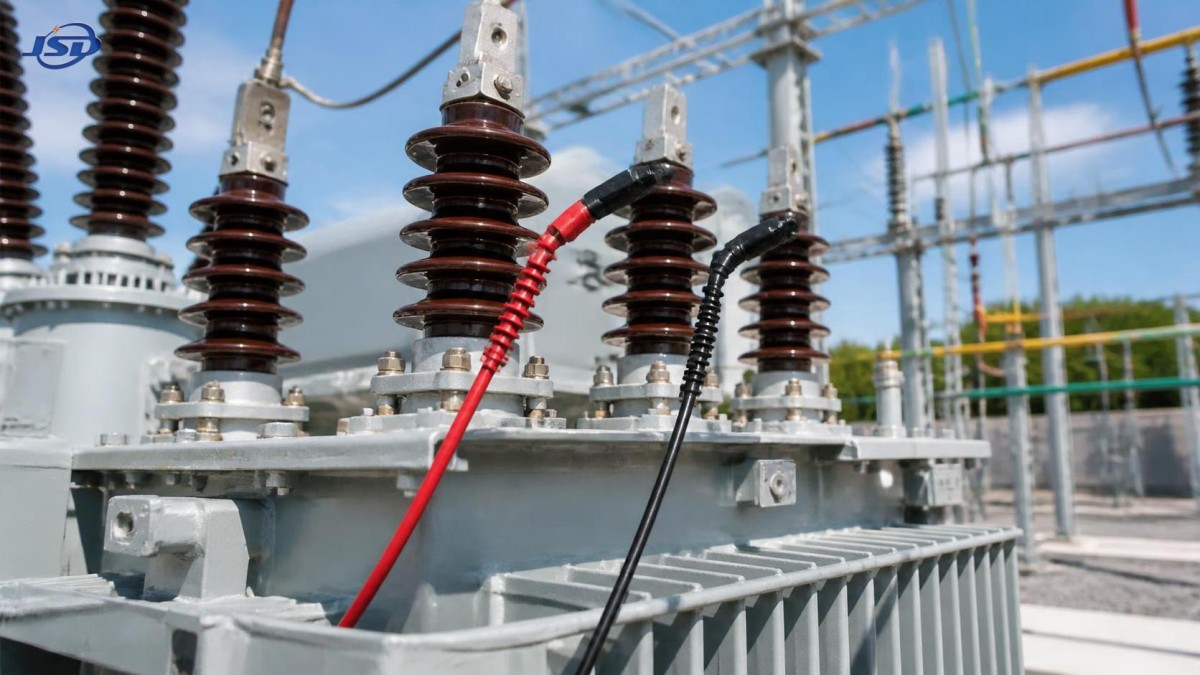
A practical test sequence begins with document review and visual inspection, then proceeds through low-voltage electrical checks, insulation diagnostics, functional tests, and final protection verification.
This order matters because obvious mechanical, documentation, or wiring defects should be corrected before higher-voltage testing exposes personnel or equipment to unnecessary risk.
Confirm that the approved single-line diagram, wiring drawings, protection settings, relay logic, cable schedules, and transformer test certificates are available at the work location.
Check the transformer nameplate against the project design, including rated power, voltage ratio, vector group, impedance, cooling method, frequency, tap range, and insulation levels.
Verify that all temporary construction grounds, test leads, lifting tools, packaging materials, and foreign objects have been removed before the final energization release.
Inspect bushings for cracks, contamination, oil seepage, damaged terminals, incorrect phase markings, and insufficient clearance from grounded structures or nearby conductors.
Review oil level indicators, pressure relief devices, conservator equipment, silica gel breathers, radiators, cooling fans, pumps, valves, and marshalling cabinet sealing.
For outdoor installations, confirm that surge arresters, neutral grounding equipment, cable terminations, control cabinets, fencing, warning signs, and drainage arrangements are complete.
Any unresolved deviation should be recorded on a punch list with an owner, corrective action, due date, and clear confirmation that it does not compromise energization safety.
Which Electrical Tests Confirm Transformer Insulation Health?
Insulation condition is the highest-priority concern before energizing a 110 kV transformer because dielectric failure can cause severe equipment damage and lengthy restoration work.
Insulation resistance testing is normally performed between each winding and earth, as well as between windings, using an appropriate DC test voltage and stabilized readings.
Results should be temperature-corrected where required and compared with commissioning baselines, manufacturer guidance, and the relative values obtained from the other winding combinations.
A low or unstable insulation resistance reading may indicate moisture, surface contamination, poor connections, damaged insulation, residual test grounding, or an incorrect test configuration.
Polarization index testing can provide additional information about insulation dryness and cleanliness, particularly when performed according to the approved procedure and temperature conditions.
Capacitance and dissipation factor testing, often called tan delta or power factor testing, evaluates insulation losses in windings, bushings, and associated insulation systems.
Abnormal dissipation factor results can reveal moisture ingress, aging insulation, conductive contamination, bushing deterioration, or internal defects that insulation resistance alone may not identify.
Transformer oil tests should include dielectric breakdown voltage, moisture content, acidity, interfacial tension, and dissolved gas analysis when required by project scope or storage conditions.
Oil dielectric strength confirms resistance to electrical breakdown, while moisture and dissolved gas results help identify contamination, overheating, internal arcing, or improper handling during installation.
When test results are doubtful, do not energize based on assumptions. Investigate the cause, repeat the test under controlled conditions, and obtain engineering approval.
How Do Ratio, Vector Group, and Winding Tests Prevent Incorrect Energization?
Transformer turns ratio testing verifies that the voltage relationship between high-voltage and low-voltage windings matches the nameplate ratio at each available tap position.
For a 110 kV transformer, ratio testing is especially important after transport, tap changer work, bushing replacement, internal repair, or changes to external connections.
A ratio deviation may indicate an incorrect tap position, faulty tap changer contacts, winding damage, inaccurate phase connections, or a mismatch between installed and specified equipment.
Vector group testing confirms the phase displacement and winding connection arrangement, such as star, delta, neutral availability, and phase shift between windings.
An incorrect vector group connection can create dangerous circulating currents, protection maloperation, parallel-operation problems, or phase sequence errors when the transformer is connected to the network.
Winding resistance testing checks the continuity and relative resistance of each phase winding, including the influence of tap changer contact positions and connection quality.
Resistance readings should be corrected for temperature where applicable and compared across phases, taps, factory data, and any earlier site test records.
Large phase differences or unstable readings may indicate loose terminals, poor joints, damaged conductors, defective tap changer contacts, or measurement errors requiring investigation.
Magnetic balance testing may also be used where specified to identify gross winding faults or magnetic circuit abnormalities before the unit enters service.
These tests protect against a common commissioning failure: energizing a physically installed transformer whose electrical configuration does not match the network design.
Why Tap Changer, Auxiliary, and Cooling Checks Need Equal Attention
On-load tap changers and off-circuit tap changers require dedicated inspection because incorrect operation can affect voltage regulation, contact reliability, and transformer loading capability.
Verify the actual tap position locally and remotely, then compare it with the approved commissioning setting, system voltage plan, and transformer ratio test results.
For on-load tap changers, test local and remote raise-lower commands, position indication, limit switches, motor drive operation, alarms, interlocks, and control power supply.
Inspect the tap changer oil compartment separately where applicable, because its oil condition and mechanical operation may differ from the main transformer tank.
Check all cooling stages, including fan rotation direction, pump operation, thermostat controls, automatic start signals, manual controls, alarms, and standby equipment availability.
Cooling equipment may not be required at no-load energization, but confirmed operation is essential before the transformer carries sustained load or experiences high ambient temperatures.
Test marshalling box heaters, internal lighting, terminal tightness, space heaters, cable glands, anti-condensation arrangements, and enclosure protection against water or dust ingress.
Temporary or remote power applications also require disciplined verification of the supporting power source. A properly tested transformer cannot compensate for unstable auxiliary supply conditions.
For contingency projects, the 100kW/215kWh Mobile Trailer Energy Storage System can support temporary auxiliary loads, site communications, and controlled deployment activities.
Its LiFePO4 battery design, 100 kW power rating, 215 kWh capacity, IP54 protection, and automatic fire suppression features suit demanding temporary power environments.
What Protection and Control Tests Must Be Completed?
Protection testing confirms that the transformer will trip correctly for internal faults, abnormal operating conditions, and external system events requiring isolation or alarm response.
Verify that protection relay settings match the approved coordination study, transformer rating, current transformer ratios, voltage transformer ratios, vector group, and neutral grounding arrangement.
Primary or secondary injection tests should be performed as required to validate relay pickup values, timing, logic functions, trip circuits, alarms, and event records.
Typical transformer protection functions include differential protection, restricted earth fault protection, overcurrent protection, earth fault protection, overfluxing protection, and thermal overload protection.
Test Buchholz relay alarms and trips where fitted, including gas accumulation contacts, oil surge contacts, wiring continuity, annunciation, and correct circuit breaker operation.
Pressure relief devices, sudden pressure relays, oil temperature indicators, winding temperature indicators, low oil level alarms, and cooling failure alarms require functional verification.
Trip circuit supervision should confirm that every breaker trip path is continuous, correctly labeled, securely terminated, and capable of operating from the intended DC battery supply.
Interlocking tests are equally important. Confirm that disconnect switches, earth switches, circuit breakers, transformer protection, and control permissions operate according to the approved sequence.
SCADA and remote-control checks should verify correct status indication, analog values, alarm transmission, control authority, timestamps, and communication reliability with the control center.
A protection relay may pass an isolated test yet still fail operationally because of incorrect wiring, reversed CT polarity, wrong terminal mapping, or unavailable DC control power.
How Should Grounding, Bushings, and External Connections Be Verified?
Grounding verification protects personnel and equipment by ensuring fault current has an effective path and exposed conductive parts remain at acceptable touch and step potentials.
Measure or verify the substation grounding system according to the project design, including transformer tank grounding, neutral grounding, marshalling cabinet bonding, and surge arrester earth connections.
Confirm that transformer neutral grounding equipment is installed exactly as designed, whether the system uses direct grounding, resistance grounding, reactance grounding, or an earthing transformer.
Bushing connections must be torque-checked using approved values, with suitable hardware, clean contact surfaces, correct phase identification, and no mechanical stress from connected conductors.
Inspect cable sealing ends, overhead jumpers, busbar supports, expansion connections, stress cones, corona rings, and clearance distances before applying system voltage.
Surge arrester installation should be checked for rating, phase assignment, grounding conductor length, counter connections where used, and secure electrical and mechanical termination.
Measure continuity across grounding bonds and verify that no accidental bonds, temporary links, or unintended neutral-earth connections remain from earlier construction or test work.
Safety managers should require a documented final walkdown involving construction, commissioning, operations, quality, and safety representatives before authorization to energize.
What Should the Final Energization Release Include?
The final release should be a formal decision based on evidence, not an informal statement that the transformer appears ready or that the schedule demands energization.
Compile a commissioning dossier containing factory test certificates, site routine test reports, oil analysis, protection test records, wiring checks, calibration certificates, and approved drawings.
Document every nonconformance, corrective action, retest result, engineering concession, and outstanding item, clearly distinguishing operational restrictions from genuine energization blockers.
Before energization, hold a briefing covering switching responsibilities, communication channels, emergency actions, exclusion zones, expected indications, and the criteria for aborting the operation.
Initial energization should be monitored for inrush current, relay behavior, abnormal noise, vibration, oil leakage, gas relay operation, voltage ratio, and phase sequence.
After energization, inspect the transformer again under voltage, then repeat observations after load is applied and cooling equipment begins normal service operation.
A 110 kV transformer should be energized only when insulation, ratio, winding, oil, protection, grounding, auxiliary, and external connection evidence forms a consistent acceptance record.
For quality control and safety managers, that disciplined record is the strongest safeguard against preventable failures, unsafe switching events, and costly loss of service.

Get a Quote
Regardless of whether you require general advice or specific support, we are happy to help you.
Send Us Your Inquiry Today

Jinshida Electric remains committed to contributing to global energy development through professional manufacturing and superior service.