





How 35 kV transformer insulation coordination limits surge risk
How 35 kV Transformer Insulation Coordination Limits Surge Risk
For a 35 kV transformer, insulation coordination is not simply a matter of selecting a higher dielectric withstand rating. It is the process of matching transformer insulation, surge arresters, system grounding, line configuration, and operating conditions so that the insulation is exposed to a controllable level of stress during lightning and switching events. Done well, it prevents the most damaging overvoltages from reaching vulnerable winding sections, bushings, cable terminations, and connected switchgear. Done poorly, it can leave apparently compliant equipment exposed to repeated dielectric ageing or a single severe failure.
Technical evaluators often face a practical tension: excessive conservatism can increase transformer cost and physical size, while an under-specified insulation system may create risks that do not become visible until commissioning or years of operation. The objective is therefore not “maximum insulation.” It is a coordinated protection level with a defensible margin, confirmed against the actual network rather than assumed from nominal voltage alone.
Nominal voltage does not define the full surge duty
A 35 kV transformer is commonly associated with a highest system voltage of 36 kV, but nominal voltage is only the starting point for insulation selection. The transformer may be connected to an overhead feeder in a lightning-prone area, a compact cable network, a wind or solar collection system, or an industrial bus supplying large motors and power-electronic loads. Each arrangement produces a different transient environment.
Lightning surges are usually the first concern where overhead lines enter a substation or terminate close to transformer bushings. A strike can create a steep-front traveling wave that is reflected and amplified at discontinuities such as line-to-cable transitions, open terminals, and transformer connections. The voltage at the transformer terminal may therefore differ substantially from the surge initially measured or calculated on the line.
Switching operations also matter. Vacuum circuit breakers, capacitor banks, cable circuits, reactors, and fault-clearing events can generate oscillatory or steep transients. Although switching surges at medium voltage are often less severe than lightning impulses in peak magnitude, they may be relevant where transformer windings are connected through short cable sections, where surge arresters are remote, or where frequent switching occurs. In converter-fed industrial systems, the evaluator should also distinguish conventional network surges from repetitive electrical stress associated with the wider power-electronic installation.
The insulation coordination chain
A sound evaluation follows the entire path of the surge rather than treating the transformer as an isolated component. The basic chain is straightforward: estimate the overvoltage that can occur at the transformer terminals, determine what the protection device will actually limit it to, account for installation effects, and compare that resulting stress with the transformer’s assigned withstand capability.
In IEC-based projects, IEC 60071 provides the broader framework for insulation coordination, while IEC 60076 addresses power transformer requirements and dielectric testing. The applicable parts and editions, as well as local grid rules, must be checked for the specific project. These documents do not remove engineering judgment; they establish a common language for insulation levels, withstand tests, clearances, protective levels, and coordination margins.
The transformer’s external and internal insulation should both be considered. External insulation includes bushings and air clearances, which can be affected by contamination, altitude, humidity, and installation geometry. Internal insulation includes winding-to-ground, winding-to-winding, lead, tap connection, and inter-turn regions. A transformer can pass its specified lightning impulse test and still face an unfavorable field condition if a poorly located arrester or long lead allows an excessively steep wave to reach the terminal.
Protection level is more useful than arrester nameplate voltage alone
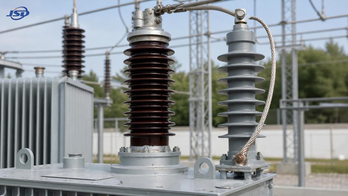
Metal-oxide surge arresters are central to most 35 kV insulation coordination schemes, but selecting one merely by its rated voltage is incomplete. The relevant value is the residual or protective voltage under the expected surge current and waveform, together with temporary overvoltage capability and energy duty. The arrester must survive likely system conditions while clamping the transformer terminal to a level below the selected insulation withstand level with an adequate margin.
Lead length is not a minor installation detail. During a fast transient, the inductance of conductor leads creates an additional voltage drop. An arrester mounted several metres away can protect the feeder but provide less protection at the transformer bushing than its catalog protective level suggests. Short, direct connections and a low-impedance earth path are often more valuable than moving to a nominally stronger arrester without improving the physical layout.
Grounding also changes the decision. In effectively grounded systems, phase-to-earth temporary overvoltage behavior differs from that of isolated, resistance-grounded, or resonant-earthed networks. The arrester continuous operating voltage, its temporary overvoltage rating, and the fault-clearing time need to be compatible with the actual grounding method. This is one area where generic 35 kV assumptions are frequently unsafe.
Where transformer design and system design meet
The insulation level requested in a transformer specification should be traceable to the network study and the protection arrangement. A tender document that simply states “35 kV transformer” without defining highest voltage, insulation withstand levels, neutral treatment, incoming connection type, and arrester location leaves too much open to interpretation. This is especially important for special-duty transformers, where load behavior and connected equipment can alter the practical surge environment.
For example, a rectifier installation may require electrical isolation, a customized low-voltage secondary arrangement, and a vector group chosen to support the rectifier system. These features should be reviewed alongside the high-voltage insulation duty, not in a separate commercial discussion. A 35 kV Isolation and Rectifier Special Transformer can be configured for three-phase applications from 50 kVA to 5000 kVA, with 50 Hz or 60 Hz operation, copper windings, and indoor or outdoor installation options. Where IEC 60076 is specified, the insulation and test requirements still need to be aligned with the actual system study, the connection arrangement, and the selected arresters.
Rectifier transformers used in metallurgy, electrolysis, electroplating, rail transit, chemical processing, mining, and other power-electronic applications also call for attention to non-surge stresses. Harmonic current, thermal loading, DC bias risks in related equipment, and switching frequency may affect winding and insulation ageing. These are not substitutes for lightning impulse coordination, but they influence the durability of the insulation system that must withstand those impulses over its service life.
A practical review of coordination margin
The margin between transformer withstand capability and the expected protective level is the heart of the review. It should not be evaluated by comparing two isolated catalog values. The expected stress at the transformer terminal may include arrester residual voltage, lead-induced voltage, wave reflection effects, and the uncertainty associated with installation and system parameters. The selected withstand level must cover that resulting stress under the relevant impulse condition.
A useful technical question is: “What voltage will the transformer bushing actually see during the credible event?” That question directs attention to the things that often get missed: cable length between arrester and transformer, overhead-line exposure, station layout, grounding conductor routing, transformer neutral configuration, and whether the arrester is fitted on all required terminals. It also avoids a common mistake—assuming that a transformer’s standard test level automatically guarantees adequate protection in every field installation.
For higher-consequence installations, transient studies may be warranted. The required study depth depends on the network complexity and risk profile. A simple radial overhead feeder may need a focused review of lightning exposure and arrester placement. A substation with cable transitions, multiple sources, capacitor switching, long feeders, or converter equipment may justify more detailed modeling. The study should identify assumptions clearly, because its result is only as reliable as the feeder configuration, grounding data, and protective-device inputs used.
Questions worth resolving before release to manufacture
- What are the highest system voltage and grounding arrangement, including credible temporary overvoltage conditions?
- Are the incoming and outgoing connections overhead line, cable, bus duct, or a combination of these?
- Which lightning impulse and power-frequency withstand levels are required by the governing specification or standard?
- Where will arresters be installed, and what is the approximate lead length to each protected transformer terminal?
- Does the transformer include a tertiary, accessible neutral, tap changer, or special secondary arrangement that requires separate consideration?
- Are altitude, pollution severity, indoor enclosure conditions, or outdoor clearances relevant to external insulation selection?
These questions are not paperwork. They determine whether the manufacturer, system designer, and commissioning team are working from the same insulation coordination basis. Late changes to arrester location or cable routing can invalidate an otherwise reasonable original calculation.
Testing confirms a design; it does not replace coordination
Factory dielectric tests remain essential. They provide evidence that the transformer has been built to withstand the specified test duty and that the insulation structure is free of certain manufacturing defects. However, a test certificate does not prove that surge arresters are correctly selected, that their grounding is adequate, or that the station layout will prevent damaging terminal stress. Those are system-level responsibilities.
Conversely, a well-prepared insulation coordination study should not be used to relax factory quality control. Reliable performance depends on both sides: disciplined design and manufacturing of insulation structures, plus proper application in the field. Jinshida Electric Power Technology Co., Ltd. approaches this through technical support, controlled manufacturing processes, and quality management for transmission and distribution equipment intended for industrial, grid, new-energy, and infrastructure applications. For an evaluator, the useful evidence is the clarity of the approved technical schedule, drawings, test scope, and documented interface responsibilities.
The decision is made at the interfaces
Surge risk in a 35 kV transformer is limited when insulation withstand levels, arrester protective characteristics, installation geometry, and grounding behavior are considered as one coordinated system. The most expensive error is often not choosing an inadequate transformer in isolation; it is overlooking the interface between a suitable transformer and an unsuitable protection arrangement.
Before approving a design, confirm the applicable insulation standard, transformer test levels, system earthing method, arrester data, terminal layout, and cable or line configuration together. If any of those inputs remain uncertain, the coordination margin should be reviewed before manufacture and again before final installation. That discipline gives the 35 kV transformer a realistic defence against the surges it will actually encounter.

Get a Quote
Regardless of whether you require general advice or specific support, we are happy to help you.
Send Us Your Inquiry Today

Jinshida Electric remains committed to contributing to global energy development through professional manufacturing and superior service.