





What causes a 100 kVA transformer to overheat under normal load?
What Causes a 100 kVA Transformer to Overheat Under Normal Load?
A 100 kVA transformer that overheats under normal load deserves prompt investigation. The nameplate rating may appear to be respected, yet excessive temperature can still shorten insulation life, trigger alarms, reduce available capacity, and eventually lead to a winding or connection failure. For maintenance personnel, the key point is simple: “normal load” on a meter does not always mean normal thermal conditions inside the transformer.
Heat is a normal by-product of transformer operation. Core losses exist whenever the unit is energized, while winding losses rise with current. A healthy transformer is designed to dissipate this heat within its specified temperature-rise limits. Overheating begins when losses become abnormally high, cooling becomes inadequate, or the actual electrical duty differs from what the load reading suggests.
The first response should not be to assume the transformer is undersized. Capacity can be part of the problem, but it is only one possibility. A practical diagnosis compares phase current, voltage, ambient conditions, ventilation, terminal temperature, protection records, and load characteristics before deciding whether repair, derating, or replacement is necessary.
Start by defining what “normal load” really means
For a three-phase 100 kVA transformer, the rated current depends on the voltage side being measured. At a 0.4 kV secondary, the full-load current is approximately 144 A. A reading below that value may look acceptable, but current alone does not show the complete thermal picture. The transformer may be experiencing phase imbalance, harmonic current, poor power quality, or an elevated ambient temperature that was not considered in the original installation.
A short loading snapshot can also be misleading. Thermal stress develops over time. A transformer operating at a moderate current for several hours in a hot, enclosed electrical room can run hotter than one briefly loaded near its rated level in a cool, well-ventilated location. Review the load profile over a full operating cycle where possible, especially in facilities with shift changes, motor starts, charging loads, or intermittent process equipment.
It is also important to distinguish the temperature being reported. A hot enclosure, a localized terminal hot spot, a high winding-temperature indication, and a high core temperature do not point to exactly the same root cause. Maintenance decisions become much more reliable when the location of the heat is identified before any major intervention.
Restricted ventilation is often the most visible cause
Dry-type transformers depend on surrounding air to remove heat. Dust-clogged air passages, blocked louvers, inadequate room openings, nearby walls, cable trays, or stored materials can all reduce airflow. In some electrical rooms, the transformer itself is sound, but the room temperature steadily rises because the heat has nowhere to go. The result is a self-reinforcing condition: hot intake air reduces cooling effectiveness, and the transformer then adds more heat to the room.
A site inspection should cover the full air path rather than only the front of the enclosure. Check whether intake and exhaust openings are clean, whether fans are rotating in the intended direction, and whether heated discharge air is being drawn back toward the transformer. In dusty industrial plants, cement handling areas, mines, and workshops, contamination can build up faster than routine visual inspections suggest. Conduct cleaning only under appropriate isolation procedures and follow the manufacturer’s instructions so that insulation surfaces and sensitive components are not damaged.
Ambient temperature matters as much as airflow. A unit installed in a plant room near boilers, compressors, or process equipment may operate in conditions that differ substantially from the original design assumptions. If overheating occurs mainly in summer or only during peak production hours, the electrical room environment should be investigated before changing the transformer rating.
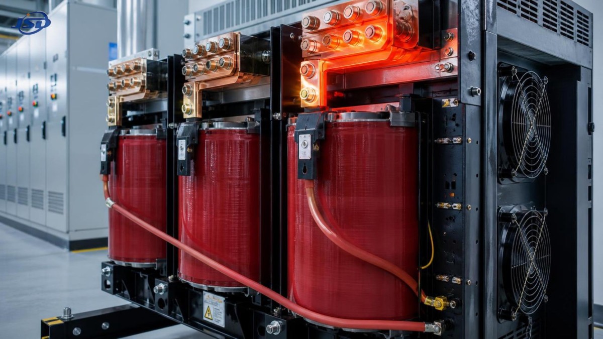
Loose connections create concentrated heat that load meters miss
A loose or oxidized connection increases contact resistance. Even when the transformer current remains within the expected range, the I²R loss at that single point can become severe. Secondary terminals, cable lugs, busbar joints, tap links, and neutral connections are common inspection points. The warning signs may include discoloration, insulation hardening, a burnt odor, uneven phase temperatures, or a localized hot spot found during infrared scanning.
Do not treat a hot terminal as merely a tightening issue. The correct torque must follow the applicable equipment documentation, and the contact surfaces, conductor size, lug type, and evidence of heat damage should all be assessed. Repeated retightening without correcting a mismatched or damaged connection can conceal a developing failure. A heavily overheated lug may have lost spring pressure or transferred heat into the terminal structure; replacement is often the safer decision.
Phase imbalance deserves the same attention. One phase may carry substantially more current because of uneven single-phase loads, a faulty downstream circuit, or an incorrect connection arrangement. The transformer’s total kVA can appear reasonable while one winding section is overloaded. Compare all three phase currents under stable operating conditions and investigate the downstream distribution board if the imbalance is persistent.
Harmonics and distorted loads can raise winding losses
Modern facilities often supply non-linear loads: variable-speed drives, UPS systems, rectifiers, LED lighting, welding equipment, battery chargers, and IT power supplies. These loads can introduce harmonic currents that increase additional losses in windings, leads, and structural parts. A standard current reading may not reveal the harmonic content responsible for the extra heating.
This is particularly relevant when a previously stable 100 kVA transformer begins to run hot after a facility upgrade. The transformer may not have changed, but the load has. A power-quality assessment can help identify total harmonic distortion, neutral loading, waveform distortion, and harmonic orders that may require derating, filtering, revised load allocation, or a transformer designed for the duty. Avoid assuming that a low power factor alone causes overheating; it is the actual current, waveform, losses, and thermal design that need to be evaluated together.
For installations with high harmonic content or restricted indoor space, equipment selection should include the cooling method, insulation system, loss values, and temperature-monitoring arrangement—not only the kVA rating. Jinshida Electric Power Technology Co., Ltd. applies this project-based approach across power distribution applications, combining technical review, manufacturing control, and practical operating requirements rather than treating capacity as the only selection criterion.
Cooling-system faults may be intermittent
Where forced-air cooling is installed, failed fans, damaged fan wiring, defective thermostatic controls, or incorrect temperature-controller settings can leave the transformer operating without the cooling capacity assumed by the design. Because fans may run only after a temperature threshold is reached, a quick inspection during cool conditions may not reveal the fault. Review alarm history and observe the fan sequence during a controlled operating period when permitted.
Temperature sensors should also be treated as maintenance items. A failed sensor can either create a false alarm or, more seriously, prevent cooling and trip logic from responding correctly. Compare controller readings with calibrated measurements where site procedures allow. If one sensor consistently differs from the others, investigate the sensor location, wiring, controller input, and the possibility of a genuine local winding hot spot.
For example, the SCB10-12 range in the 10kV Cast Resin Dry-Type Distribution Transformer line is available from 30 to 2500 kVA and can be equipped with temperature protection and control. Its stated forced-air operating capability is up to 120% of rated load under the relevant condition, but that should never be interpreted as permission to bypass room ventilation, sensor checks, or fan maintenance. Forced-air capacity is a defined operating arrangement, not a substitute for thermal discipline.
Voltage conditions and internal losses should not be overlooked
Sustained overvoltage can increase core flux and core loss, producing higher no-load heating even when the secondary load is light. Incorrect tap position, a changed upstream supply condition, or a commissioning error can contribute. Measure primary and secondary voltages, verify the selected tap against the actual supply, and compare findings with the transformer documentation. Tap changes must be performed only with the required isolation and approved procedures.
Internal faults are less common than ventilation or connection problems, but they require serious attention. Deteriorated insulation, winding displacement after a fault event, partial discharge, poor impregnation or casting integrity, and damage from moisture or contamination can create abnormal losses and hot spots. Unusual noise, a rapidly rising temperature at relatively stable load, repeated insulation alarms, or evidence of tracking should move the investigation beyond routine cleaning and tightening.
For cast-resin units, visual inspection may reveal cracks, surface contamination, or tracking marks, but it cannot confirm every internal condition. Insulation-resistance testing, winding-resistance comparison, transformer turns-ratio testing, thermography, and other diagnostic work should be selected by qualified personnel based on the transformer type, outage window, and suspected failure mode. Test results are most useful when compared with prior commissioning or maintenance records rather than viewed in isolation.
A practical troubleshooting sequence
When a transformer temperature alarm occurs, begin with safe operational facts: record the time, active load, phase currents, voltages, ambient temperature, fan status, and alarm values. Then inspect for blocked airflow, abnormal noise, odor, enclosure damage, and visible hot connections. Infrared thermography, performed with suitable safety controls, is especially valuable because it distinguishes a broad thermal problem from one or two concentrated defects.
Next, compare the current condition with baseline information. Was the transformer recently energized after maintenance? Has a new drive system, UPS, production line, or charging equipment been added? Did ventilation equipment fail, or was the room layout changed? A good maintenance record often identifies the change that made a formerly acceptable installation run hot.
If the temperature remains high after airflow and external connections are confirmed, avoid prolonged operation based only on the assumption that the load is below 100 kVA. Escalate for electrical testing and engineering review. Continuing operation through unexplained overheating can accelerate insulation ageing and turn a manageable fault into an outage.
Prevent repeat overheating through installation and maintenance discipline
The most effective prevention is to maintain a usable baseline: commissioning temperatures, expected load profile, phase-current balance, tap setting, torque records, and thermographic images of healthy connections. These references make future changes easier to detect. Scheduled cleaning and ventilation checks should reflect the actual site environment, not just a generic calendar interval.
When replacement or expansion is being considered, review the entire duty cycle: upstream voltage, secondary voltage, load growth, harmonic sources, indoor ambient conditions, fire-performance requirements, and monitoring needs. Jinshida Electric Power Technology Co., Ltd. supports distribution equipment applications for industrial manufacturing, commercial facilities, grid-related projects, renewable energy systems, and infrastructure. For a 100 kVA transformer installation, the useful question is not simply whether the nameplate is large enough, but whether the selected design, cooling arrangement, and operating environment are compatible over the equipment’s working life.
A transformer that overheats under apparently normal load is usually communicating a specific problem: trapped heat, resistance at a connection, distorted current, missing cooling, unsuitable voltage conditions, or deteriorating insulation. Find where the heat is concentrated, verify what the electrical measurements leave out, and correct the root cause before relying on a larger rating as the answer.

Get a Quote
Regardless of whether you require general advice or specific support, we are happy to help you.
Send Us Your Inquiry Today

Jinshida Electric remains committed to contributing to global energy development through professional manufacturing and superior service.