





Selecting a 250 kVA transformer for commercial building peak load
A commercial building can appear comfortably sized on paper and still create a difficult transformer decision. The problem usually surfaces when the electrical schedule is nearly complete: lifts, HVAC units, kitchen equipment, lighting, pumps, tenant power, and IT loads all feed into a demand calculation, and a 250 kVA transformer looks like the obvious match. Then someone asks whether the figure represents normal demand, the true coincident peak, or a capacity allowance that has already been used elsewhere in the calculation.
This matters because a transformer that is too close to its sustained operating limit may run hotter, leave little room for a new tenant load, and make voltage-drop complaints harder to diagnose. Selecting too large a unit is not automatically safer either. It can increase initial cost, require more space, and add no-load energy losses that occur whenever the transformer is energized. The practical task is to choose capacity from the building’s actual load behavior, not from one attractive number in a spreadsheet.
Start with the load profile, not the connected-load total
Connected load is the sum of all nameplate ratings. It is useful for making sure nothing has been omitted, but it is rarely the correct number for transformer capacity. In a commercial building, some loads cycle, some operate only during business hours, and some have predictable but brief peaks. A restaurant tenant may create a different evening demand pattern from an office floor. A building with chilled-water equipment may peak during hot weather, while a retail unit may peak when lighting, display equipment, and air conditioning operate together.
The more useful figure is maximum demand at the transformer secondary, based on realistic simultaneity. Review the load schedule by category and ask when each group is likely to operate. Existing sites may have interval-meter data; new construction usually requires a calculation using applicable design rules, equipment duty information, and diversity assumptions approved by the electrical designer. Do not simply apply one broad diversity factor to the entire building. Large mechanical loads, life-safety loads, tenant loads, and future allowances often need separate treatment.
For a three-phase 400 V low-voltage system, transformer current can be estimated as:
Full-load current = kVA × 1,000 ÷ (√3 × line voltage)
A 250 kVA unit at 400 V provides approximately 361 A of full-load secondary current. This is a useful cross-check against the main low-voltage breaker, busbar rating, feeder arrangement, and calculated demand. It is not, by itself, proof that 250 kVA is adequate. The demand must also be assessed in kW and power factor terms. A low power factor means more kVA is required to deliver the same real power.
When 250 kVA is a reasonable starting point
A 250 kVA transformer can be a sensible selection when the calculated maximum demand, including an agreed allowance for normal near-term change, remains below the rating under the expected ambient and installation conditions. It is particularly important to distinguish between a short, occasional peak and a demand that persists for hours. A brief elevator start or motor transition does not have the same thermal effect as a fully occupied building operating near its maximum throughout an afternoon.
Many teams use a planning loading range rather than designing to continuous operation at exactly 100% of nameplate capacity. The exact target depends on the governing standards, load characteristics, ventilation, ambient temperature, harmonic content, redundancy requirements, and owner policy. The point is not to apply a universal percentage. It is to make the assumed operating margin visible and defensible.
Before accepting a 250 kVA transformer, compare these four values on the same basis:
- calculated coincident maximum demand in kVA;
- expected power factor at the time of that demand;
- future load already committed by leasing, equipment plans, or expansion drawings; and
- capacity affected by derating, site temperature, enclosure arrangement, or supply conditions.
If the demand estimate is close to the transformer rating before future loads are included, the decision should not be treated as routine. The next standard size, a second transformer, demand management, or a revised load plan may be more appropriate. Conversely, if the estimate includes conservative connected-load assumptions that are unlikely to coincide, oversizing should be justified by a clear operational need rather than habit.
Check voltage and utility interface before comparing transformer sizes
The phrase 250 kVA transformer does not define primary voltage, secondary voltage, vector group, tap range, frequency, impedance, or insulation system. These details affect whether the unit can be connected to the local network and coordinated with downstream equipment.
Obtain the utility or site supply information early. Confirm the nominal primary voltage, allowable voltage variation, fault level, metering arrangement, neutral earthing method, and utility protection requirements. On the low-voltage side, verify whether the building distribution is 400/230 V, 415/240 V, or another arrangement. A mismatch in voltage assumptions can affect equipment selection throughout the project, from switchboards to variable-speed drives.
Tap selection also deserves attention. A no-load tap changer can adjust the ratio only while the transformer is de-energized. This may be adequate where incoming voltage is stable and the commissioning setting can be selected with care. Where primary voltage variation is significant, the design team should determine whether a fixed off-circuit tap range is sufficient or whether the network arrangement requires another approach.
Impedance, fault duty, and motor starting can change the answer
Capacity sizing is only one part of the decision. Transformer impedance influences the prospective short-circuit current available on the secondary side. A lower impedance can support better voltage performance during motor starts, but it can also raise fault current and place greater duty on low-voltage switchgear and protective devices. A higher impedance may reduce fault levels, yet excessive voltage dip can become a problem when large motors start.
Commercial buildings often contain equipment that makes this trade-off visible: fire pumps, ventilation fans, lifts, booster pumps, compressors, and HVAC motors. A single direct-on-line motor start can cause a voltage dip even when average building demand appears modest. Review the starting method, motor size, starting current, cable length, and transformer impedance together. Soft starters and variable-speed drives can reduce starting demand, although they may introduce harmonic considerations that need separate evaluation.
Protection coordination should be reviewed as a system. The primary fuse or breaker, transformer protection, main low-voltage incomer, outgoing feeders, and earth-fault scheme must operate selectively where required. The transformer supplier can provide rated current, impedance, vector group, losses, and protection-related data, but final settings and coordination should be confirmed by qualified electrical engineers using the actual network parameters.
Installation conditions are part of the rating decision
A transformer performs according to its thermal environment, not only its nameplate. An indoor transformer room with restricted ventilation, nearby heat sources, or cable congestion can create a different operating condition from an outdoor packaged substation. Access for delivery, oil containment, fire separation, clearances, ventilation paths, noise limits, and maintenance access should be resolved before procurement.
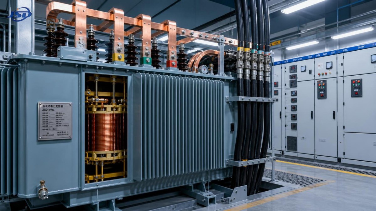
Oil-immersed equipment may be selected for distribution projects where its installation arrangement, fire strategy, and local requirements are suitable. For a 35 kV incoming supply stepped down to 0.4 kV, the 35kV/0.4kV Oil-Immersed Power Distribution Transformer is available in ratings that include 250 kVA. Its stated configuration includes copper coils, 50 Hz or 60 Hz options, no-load tap changing, and customization of voltage, connection group, and losses. These specifications need to be matched to the project’s approved single-line diagram rather than adopted as generic defaults.
Where environmental risk and fire planning are relevant, the insulating-fluid choice should be discussed at the design stage. The available information for this type of unit includes an FR3 vegetable-oil option. That may be relevant to a project’s environmental or fire-risk assessment, but it does not remove the need to follow the governing installation, containment, and authority requirements for the specific site.
Do not overlook losses over the operating life
Initial purchase price often receives more attention than energy loss, even though a transformer remains energized for long periods. No-load loss is present whenever the transformer is connected to the supply. Load loss rises with current and becomes more significant as loading increases. Two units with the same 250 kVA rating may therefore have different operating-cost implications depending on their loss design and the building’s annual load pattern.
Ask for guaranteed loss values at the applicable standard and temperature conditions, then compare them using the expected operating profile. A building that is lightly loaded overnight may place more weight on no-load losses. A site with long periods of high demand may place more weight on load losses. Avoid comparing only one number from a brochure, especially when the quoted values can vary by design standard or material specification.
Efficiency claims should also be read in context. An efficient transformer can reduce distribution losses, but correct sizing still matters. A significantly oversized unit may operate well below the load point assumed in an economic comparison. A unit with insufficient capacity may operate under thermal stress or limit future use. The best choice is usually the one that balances realistic loading, expected hours of operation, loss data, and expansion needs.
Plan for growth without treating it as an excuse for oversizing
Future capacity should be based on identifiable changes: an unleased retail bay, a planned kitchen, additional charging infrastructure, a later mechanical phase, or a known production process. Vague growth assumptions can push every upstream component beyond what the project actually needs. On the other hand, ignoring a documented phase-two load can force disruptive replacement work later.
There are several ways to keep options open. The building can reserve switchboard space and cable routes for a later transformer upgrade. The site may allow a second transformer position. Large discretionary loads can be designed for staged connection. In some applications, a higher-rated transformer is justified; in others, a modular distribution strategy is more economical and more resilient. The right decision depends on how likely the future load is, how costly an outage would be, and whether the upstream supply can accommodate expansion.
Short-term overload capability should not be used as normal design capacity. Some copper-coil oil-immersed designs state that up to 150% rated load may be tolerated for no more than two hours when oil temperature is monitored and kept within the specified limit. That kind of capability can help address occasional abnormal conditions, but it is not a substitute for adequate continuous rating, correct ventilation, and protection design.
A practical approval sequence
When the decision is approaching procurement, it helps to freeze the inputs in an order that prevents late contradictions. First, confirm the supply voltage and utility conditions. Next, validate the diversified building demand and power factor assumptions with the latest equipment schedules. Then check full-load current against the low-voltage main equipment, conduct a fault-level and protection study, and review motor-starting behavior. Only after these checks should capacity, impedance, tap range, connection group, and loss requirements be issued for quotation.
Request a dimensional drawing and total weight early enough to verify transport routes, plinth design, lifting points, room access, and foundation loading. Confirm the required standards and test documentation for the jurisdiction and project specification. If the transformer will serve essential loads, examine the complete reliability arrangement: source availability, generator interaction, automatic transfer requirements, maintenance isolation, and the consequence of a single transformer outage.
A 250 kVA transformer is a sound choice when it fits the real electrical profile and the physical installation, not merely when it matches a rounded demand figure. Treat the rating as the result of coordinated checks rather than the beginning and end of the design decision. That approach gives the building a better chance of operating reliably through normal occupancy changes, seasonal peaks, and future electrical additions.

Get a Quote
Regardless of whether you require general advice or specific support, we are happy to help you.
Send Us Your Inquiry Today

Jinshida Electric remains committed to contributing to global energy development through professional manufacturing and superior service.