





What a grounding transformer actually does in ungrounded power systems
In ungrounded power systems, “no intentional connection to earth” does not mean the system is electrically isolated in every practical sense. The network still has distributed capacitance to ground through cables, transformer windings, motors, surge arresters, and other equipment. That is exactly why grounding behavior becomes a serious design issue rather than a theoretical one. A grounding transformer is used to introduce a controlled neutral point where none naturally exists, so the system can be monitored, protected, and stabilized during abnormal conditions.
The confusion usually starts with language. Many people assume a grounding transformer is there simply to “ground the system.” In practice, its purpose is more specific: it gives a three-phase, three-wire system an artificial neutral so zero-sequence current has a return path. Once that path exists, the engineer can connect grounding resistors, reactors, relays, and fault-detection devices in a predictable way. Without that reference point, single line-to-ground faults may remain difficult to detect while healthy phases are exposed to higher voltage stress.
That distinction matters in industrial plants, utility distribution networks, renewable integration points, mining operations, and isolated process facilities where ungrounded or impedance-grounded arrangements are still used. The question is not whether grounding is conceptually good or bad. The real question is how the system behaves when the first fault occurs, how long equipment can tolerate that condition, and whether operators can locate the problem before it escalates into a second fault or an insulation failure elsewhere.
Why ungrounded systems were used in the first place
Ungrounded systems have historically been selected for continuity of service. In a simple three-phase system with no intentional earth connection, a single line-to-ground fault may not immediately cause large fault current. That means the process may keep running long enough for operators to identify the problem instead of suffering an instant shutdown. In some industries, that operating advantage was considered valuable.
But the trade-off is well known. During a ground fault on one phase, the voltage of the two healthy phases to ground can rise significantly, often approaching line-to-line voltage relative to earth. Insulation that normally sees lower phase-to-ground stress must now tolerate a much harsher condition. If transient overvoltages are present, the risk becomes more serious. In networks with long cable runs, variable-frequency equipment, or aging insulation, this operating philosophy can become expensive rather than resilient.
That is where the grounding transformer enters the picture. It does not remove every risk, but it makes the system’s fault behavior manageable.
What the grounding transformer actually does
A grounding transformer provides a neutral point on a system that otherwise has no usable neutral. The most common designs are zig-zag transformers and wye-delta transformers used specifically for grounding duty. Their role is not usually to supply normal line-to-neutral loads. Their role is to handle zero-sequence components and establish a stable reference to earth.
Under balanced normal conditions, very little current may flow through the grounding transformer. During a single line-to-ground fault, however, the device provides the path required for ground-fault current to return. This enables several essential functions:
- creation of a neutral reference for the system;
- connection of a grounding resistor or reactor to limit fault current;
- operation of protection relays based on measurable ground-fault current or voltage displacement;
- reduction of transient overvoltage exposure compared with a truly ungrounded network;
- improved fault location and system supervision.
In other words, the grounding transformer turns an ambiguous fault condition into a controlled one. That is its practical value.
Why fault detection improves after adding one
One of the biggest operating problems in ungrounded systems is not always the first fault itself, but the uncertainty around it. Because fault current can be very low, plant personnel may know a ground fault exists but still struggle to locate it quickly. The system continues operating, but now under abnormal stress. If a second ground fault occurs on another phase at a different point in the network, the result can resemble a phase-to-phase fault through ground, with far more destructive consequences.
By using a grounding transformer with a neutral grounding resistor, the designer can set a known fault current level that is high enough for dependable relay detection yet low enough to limit thermal and mechanical damage. That balance is the core of resistance grounding practice. The transformer itself is not the full solution; it is the enabling component that allows the protection scheme to work.
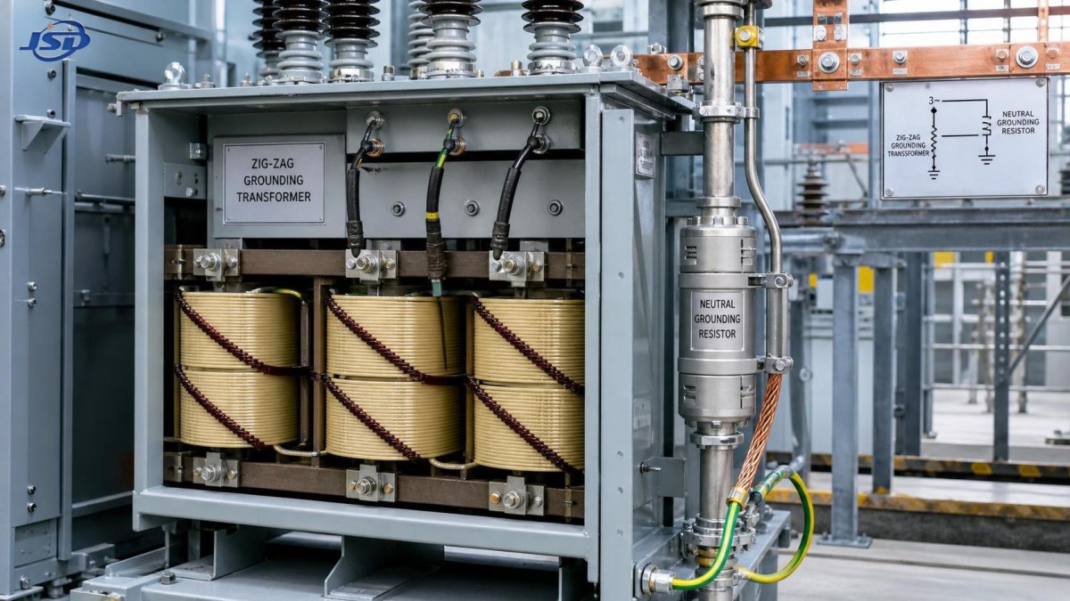
For information researchers comparing equipment categories, it helps to separate this function from standard distribution transformation. A conventional distribution unit is primarily intended to change voltage levels and feed loads. A grounding transformer is usually specified around system grounding behavior and fault-duty requirements. In some projects, both functions appear in the same substation environment. For example, a package may include a grounding arrangement alongside a voltage conversion asset such as the 30kV/0.4kV Oil-Immersed Power Distribution Transformer, but the engineering purpose of each device is different and should not be conflated during specification review.
How it helps control overvoltage risk
When engineers say a grounding transformer “stabilizes” an ungrounded system, they are usually referring to phase-to-ground voltage behavior and transient response. A system with no neutral reference can experience neutral shift during faults. The healthy phases may then see elevated voltage to ground. That added stress is especially unwelcome in networks with older motors, dry-type transformers, long shielded cable circuits, or power electronics that are already sensitive to insulation degradation.
A grounding transformer does not eliminate all surges or switching transients. Surge arresters, insulation coordination, cable design, and system layout still matter. What it does is give the network a defined relationship to earth, often through an impedance element. That reduces the “floating” character of the system and helps limit certain abnormal overvoltage conditions. In practical terms, it can improve equipment life expectancy and reduce the probability that one undetected fault turns into a broader insulation problem.
Common types: zig-zag vs. wye-delta
The two grounding transformer arrangements most often encountered are zig-zag and wye-delta.
Zig-zag grounding transformers are popular because they are compact for grounding duty and do not require a separate secondary load winding in many applications. Their winding arrangement allows zero-sequence current to flow while balancing normal three-phase conditions. For systems where the main objective is neutral creation and ground-fault current return, zig-zag is often the straightforward choice.
Wye-delta grounding transformers can also establish a neutral point, with the delta winding providing a path for zero-sequence currents. This design may be selected where there are broader system reasons for using that transformer configuration, or where auxiliary station service needs are part of the wider design concept. The selection depends on fault-duty, insulation class, physical footprint, losses, and the surrounding substation architecture.
There is no universal “better” option. The right choice depends on how the network is protected and what role the transformer is expected to perform beyond grounding alone.
What a grounding transformer does not do
This is where misunderstandings often lead to poor decisions.
A grounding transformer does not automatically make a system solidly grounded. In many cases, it is intentionally paired with a resistor or reactor so fault current is limited. It also does not replace proper relay coordination, surge protection, insulation monitoring, or cable maintenance. If the network has chronic harmonics, poor installation practices, or deteriorated switchgear, adding a grounding transformer will not fix those root causes.
It also should not be treated as a generic accessory that can be dropped into any medium-voltage system without study. The grounding method affects relay settings, arc-flash behavior, equipment ratings, temporary overvoltage performance, and compliance with project specifications. A wrong assumption here can create downstream problems in commissioning and operation.
Where it is commonly used
Grounding transformers are frequently applied where the source transformer secondary is delta-connected, where generator systems lack a neutral, or where a network extension introduces grounding requirements not addressed by the original source arrangement. Typical examples include:
- industrial plants with medium-voltage motor systems;
- mining and metals facilities where continuity and fault supervision are both important;
- wind and solar collection systems, depending on project design philosophy;
- utility distribution substations requiring a grounding point on a three-wire system;
- temporary or modular power systems where a dedicated neutral reference must be added.
In these settings, the grounding transformer is often part of a larger protection strategy rather than a standalone purchase decision. That is why project documentation usually matters more than catalog familiarity.
What specifiers and buyers should look at
For readers in the early research stage, the most useful question is not “Which grounding transformer is best?” but “What grounding objective does the project require?” The answer determines the rest.
Key review points typically include:
- system voltage and frequency;
- available fault levels and desired ground-fault current;
- whether neutral grounding will be through resistance, reactance, or another method;
- continuous versus short-time thermal rating of the transformer;
- indoor or outdoor installation conditions;
- insulation level and environmental duty;
- relay coordination and monitoring requirements;
- applicable standards and utility or end-user specifications.
Procurement teams sometimes focus heavily on transformer price while underweighting the protection design around it. That is risky. An apparently lower-cost unit may not align with the required fault duration rating, enclosure design, or accessory package. In international sourcing, documentation quality, test records, and engineering responsiveness can be as important as manufacturing cost, especially when the device will be tied to a custom grounding resistor and protection scheme.
Where a project also includes distribution transformation assets such as a 30kV/0.4kV Oil-Immersed Power Distribution Transformer, stakeholders should confirm whether the grounding solution is integrated at the system level or handled by separate equipment packages. This prevents a common early-stage mistake: assuming the presence of a distribution transformer automatically resolves neutral grounding requirements everywhere in the network.
Standards and verification: proceed carefully
Grounding transformer design and application are normally tied to recognized electrical standards, but the exact governing documents depend on region, voltage class, and project type. IEEE, IEC, and utility-specific specifications may all be relevant. Because standard applicability varies, any project-level claim about compliance should be checked against the actual bid package and local code requirements rather than assumed from general product literature. Where details are unclear, the correct position is 【待核实】 until confirmed.
Testing also deserves attention. Buyers should expect routine test documentation appropriate to the transformer type, and where the grounding package includes a resistor or relay panel, the coordination between components should be reviewed rather than evaluated in isolation.
The bigger takeaway
A grounding transformer is important not because it is exotic, but because it makes system behavior predictable. In an ungrounded power system, that predictability is what turns a hidden vulnerability into an engineered protection approach. It creates a neutral where none exists, supports controlled ground-fault current, improves fault detection, and helps reduce the overvoltage exposure that otherwise accompanies a floating system.
For anyone researching the topic at a foundational level, the main point is simple: the value of a grounding transformer is not in “adding ground” as a checkbox. Its value lies in how it changes fault performance, protection coordination, and insulation stress across the whole network. That is why it remains a relevant device in modern power distribution, especially where reliability and fault manageability must be balanced rather than treated as separate goals.

Get a Quote
Regardless of whether you require general advice or specific support, we are happy to help you.
Send Us Your Inquiry Today

Jinshida Electric remains committed to contributing to global energy development through professional manufacturing and superior service.