





Transformer Losses Explained: Core Loss vs Copper Loss in Efficiency Evaluation
Efficiency evaluation starts with separating no-load loss from load-dependent loss. In transformer terms, that means distinguishing core loss from copper loss before comparing ratings, test sheets, or operating cost assumptions. If these two terms are treated as interchangeable, the assessment quickly drifts off course, especially when the unit will run with variable loading, harmonic content, or long daily energized hours. A transformer can show low loss at one operating point and still perform poorly at another because the physical sources of loss are different and they respond to voltage, frequency, and current in different ways.
Core loss, often called iron loss or no-load loss, is the power dissipated in the magnetic core whenever rated voltage is applied. It exists even when the secondary is open and no useful load is connected. Copper loss, by contrast, is created by current flowing through the windings and related conductive parts. It rises with load and becomes the dominant loss component as current increases. For a technical review, the first useful question is not which loss is “more important,” but under which operating profile each loss will dominate the lifetime energy picture.
What Core Loss Really Includes
Core loss is usually discussed as a single value on a nameplate or test report, but it comes from several magnetic mechanisms inside the laminated steel or other core material. The two main components are hysteresis loss and eddy current loss. Hysteresis loss is linked to repeated magnetization reversal in each voltage cycle. Eddy current loss comes from circulating currents induced within the core material itself. Both are influenced by flux density, frequency, lamination thickness, insulation between laminations, and the magnetic quality of the steel.
Because core loss is tied mainly to applied voltage and frequency, it remains relatively stable over changing load as long as the voltage waveform and frequency stay close to design conditions. That stability often causes misunderstanding. “Stable” does not mean “small.” In a distribution application where the transformer is energized continuously but lightly loaded for long periods, no-load loss can account for a large share of annual energy dissipation. In another installation with short energization periods and heavy current peaks, copper loss may dominate instead.
During factory evaluation, core loss is normally measured in a no-load test at rated frequency and specified voltage. The reading can be distorted by waveform quality in the test supply. Even a modest harmonic content in the applied voltage may push measured core loss above the value expected under sinusoidal conditions. That is why test interpretation should include attention to the voltage wave shape, not only the final watt value.
How Copper Loss Develops Under Load
Copper loss is commonly identified with I²R loss in the primary and secondary windings. The principle is straightforward: resistance converts electrical energy into heat as current passes through the conductor. Yet practical evaluation is less simple because winding resistance changes with temperature, and transformer winding temperature can shift significantly between a cold factory measurement and real service conditions. A low resistance measured at ambient temperature does not represent the hot condition reached after sustained loading.
Additional stray load losses are often grouped near copper loss in practical assessments because they also increase with current. These losses appear in structural metal parts, winding conductors affected by leakage flux, clamping components, tank walls, and lead connections. If they are ignored, the total load loss estimate may look cleaner than the actual operating result. This point matters when comparing units with different winding geometries, conductor transposition methods, insulation spacing, or mechanical layouts.
A simple comparison illustrates the difference in behavior. If load current doubles, ideal copper loss rises by roughly four times because of the square relationship. Core loss does not follow that current pattern. It remains tied mainly to the voltage and magnetic design. This is why a transformer selected only on full-load efficiency may not be the best choice for a site that spends most of its time far below rated output.
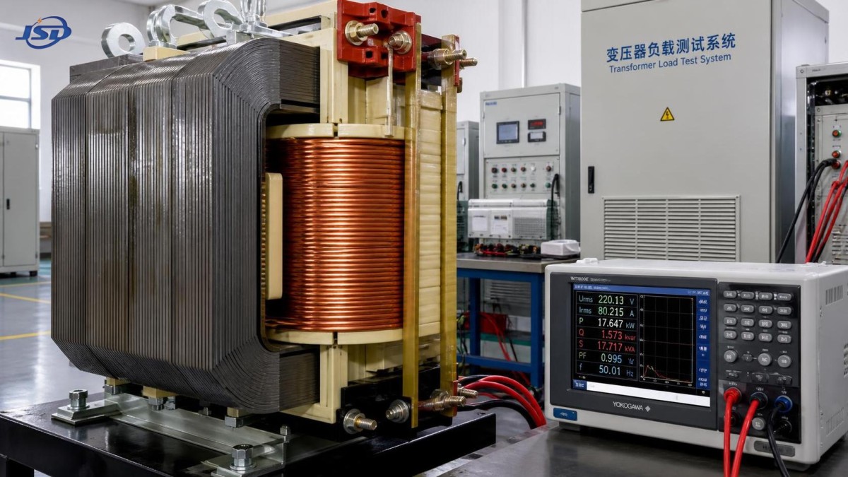
Why the Distinction Changes Efficiency Evaluation
Transformer efficiency is the ratio between output power and the sum of output power plus total losses. That formula is simple, but the result depends heavily on loading assumptions. A unit with very low core loss and somewhat higher winding loss may perform well in systems that stay energized around the clock with moderate current. Another design with higher no-load loss but lower load loss may compare favorably when current remains high for long operating blocks. Without a realistic load curve, a single efficiency figure can mislead more than it informs.
That is also why standards and tender documents often separate no-load loss and load loss instead of accepting only one headline efficiency percentage. Two transformers can report similar efficiency at a selected point while producing different thermal behavior and different annual energy use. The split values make the tradeoff visible. They also make it easier to review whether the design emphasis is on magnetic material quality, conductor sizing, cooling path, or a balance of all three.
Another common error is evaluating losses at rated load only, then applying that conclusion to renewable integration, industrial cyclic duty, or infrastructure with seasonal underloading. In such conditions, average current may stay far below rated current for long periods, while energization remains continuous. The result is that core loss becomes proportionally more significant than many quick comparisons assume.
Design Variables Behind the Numbers
Core loss is strongly affected by material choice and magnetic flux density. Grain-oriented electrical steel, improved lamination coating, tighter stacking quality, and a conservative flux design can reduce no-load loss, though they may affect size, mass, or cost. Manufacturing details matter as well. Burrs at cut edges, poor step-lap assembly, uneven clamping pressure, or damage to lamination insulation during fabrication can increase local eddy currents and shift measured loss upward.
Copper loss depends on conductor material, cross-sectional area, current density, winding arrangement, connection quality, and cooling effectiveness. Larger conductor sections reduce resistance, but they also influence winding dimensions and leakage reactance. In foil or strip windings, edge condition and layer insulation placement can affect current distribution. In cast resin dry-type units, thermal behavior is especially relevant because winding temperature has a direct impact on resistance under service load. That makes temperature rise data and ventilation assumptions part of loss interpretation, not a separate topic.
For medium-voltage indoor installations, a design such as the 33kV Cast Resin Dry-Type Distribution Transformer may be discussed in the context of load loss and thermal stability together, since dry-type construction avoids oil but places more attention on enclosure conditions, airflow path, and ambient temperature when evaluating hot winding resistance and sustained efficiency.
Interpreting Test Reports Without Shortcut Assumptions
No-load loss values should be read alongside the test voltage, frequency, and tap position. A transformer measured on a non-principal tap can show different magnetic conditions from the nominal operating point. Load loss values should be checked for the reference temperature at which they are corrected. A comparison between one report corrected to a standard hot resistance basis and another left closer to ambient is not a meaningful engineering comparison.
Transport and installation conditions can also influence post-delivery verification. Mechanical shock during shipping may not create an obvious external defect, yet it can alter internal alignment, loosen clamping, or affect contact pressure in ways that later change vibration, noise, or loss behavior. On-site acceptance testing should therefore be interpreted with the installation state in mind: cable terminations, phase balance, ventilation obstruction, and supply waveform quality all shape the measured result.
Where harmonic-rich loads are expected, standard sinusoidal loss values should not be treated as complete operating truth. Harmonics can raise stray load loss and local heating beyond the basic nameplate picture. Current distortion from rectifiers, variable-frequency drives, and some conversion equipment can change the effective burden on windings even when RMS current appears manageable at first glance. In that setting, a purely catalog-based comparison is usually too shallow.
Frequent Misreadings in Technical Reviews
One recurring mistake is to assume that lower total loss in a datasheet always means lower operating temperature under every condition. A transformer with lower no-load loss but higher load loss can run hotter when heavily loaded, while a design with higher no-load loss may remain thermally calmer near full current because of lower winding resistance or better heat dissipation. The loss split matters.
Another issue appears when procurement documents request “lowest loss” without defining the loading profile, duty cycle, ambient range, altitude, or cooling restrictions. The result may be bids optimized around a test point that does not match actual service. A technically sound evaluation usually requires at least these inputs to be settled before loss values are ranked:
- expected energization hours and whether the transformer stays live during light-demand periods,
- approximate load pattern rather than a single peak number,
- supply frequency stability and any known waveform distortion,
- space constraints that may affect ventilation, enclosure choice, or allowable temperature rise,
- the intended tap operating position if it differs often from nominal.
Even with good data, there is still room for caution. Published loss figures are tied to defined test conditions. Once the transformer is installed in a room with dust accumulation, blocked air passages, elevated ambient temperature, or unbalanced phases, real efficiency may depart from laboratory expectations. That does not mean the original values were wrong; it means the operating context changed the balance between electrical and thermal behavior.
Maintenance and Long-Term Stability
Core loss normally does not drift sharply during service unless the magnetic circuit is damaged, overheated, or mechanically disturbed. Copper-related loss can shift more visibly because connection resistance, winding temperature, and cooling performance change with service conditions. Loose terminations, oxidized joints, clogged ventilation paths, or persistent overloading can all increase effective load loss and local hot spots. In dry-type units, contamination on surfaces may also alter cooling performance and partial discharge behavior, which then affects thermal stability even if the original resistance values were acceptable.
This is why maintenance records should be read together with loss concerns. A rise in operating temperature at similar load, recurring odor during peak demand, or abnormal enclosure heat pattern may point toward increased load loss or restricted cooling rather than a pure insulation problem. Separating those possibilities early makes troubleshooting more efficient and reduces the risk of replacing the wrong component or misclassifying the cause.
Where Evaluation Becomes More Reliable
The most dependable efficiency judgment comes from aligning loss components with the actual duty of the transformer, then checking whether the design details support that duty. Core loss speaks to what the unit costs electrically just by being energized. Copper loss speaks to what it costs when current is delivered. The two values are not rivals on a datasheet; they describe different parts of the operating reality. Once that distinction is kept intact, comparisons between transformer designs become more technically sound, especially where load variation, indoor thermal limits, or harmonic exposure would otherwise hide the real efficiency picture.

Get a Quote
Regardless of whether you require general advice or specific support, we are happy to help you.
Send Us Your Inquiry Today

Jinshida Electric remains committed to contributing to global energy development through professional manufacturing and superior service.