





How to plan cable sizing for a 400 kVA open frame genset
How to Plan Cable Sizing for a 400 kVA Open Frame Genset
Planning cable sizing for a 400 kVA open frame genset is not a matter of opening an ampacity table and selecting the first conductor that appears large enough. At this rating, small assumptions can become expensive mistakes: a cable route that is hotter than expected, a long feeder with excessive voltage drop, an undersized neutral serving nonlinear loads, or parallel conductors that cannot be installed with equal impedance.
For technical evaluators, the right approach is to start from the generator’s actual operating conditions rather than its nameplate alone. Generator voltage, load composition, installation method, route length, derating factors, protection settings, earthing arrangement, and the upstream or downstream transformer configuration all affect the final cable design. A 400 kva open frame genset used for a construction pump station does not need the same cable arrangement as one supporting a hospital transfer system, a mining conveyor, or a temporary data-center load bank.
The goal is simple: deliver the generator’s available power safely and reliably without creating a weak point in the distribution system. The calculations are straightforward in principle. The judgment lies in knowing which project conditions will change them.
Begin with the generator output current, not the kVA label
For a three-phase generator, the nominal line current is calculated as:
Current (A) = kVA × 1,000 ÷ (√3 × line-to-line voltage)
A 400 kVA set at 400 V produces approximately 577 A at full rated output. At 415 V, the figure is about 556 A. At 480 V, it falls to roughly 481 A. This difference matters. A cable schedule copied from a 400 V project can be unnecessarily large or, more dangerously, inadequate if the actual low-voltage bus operates at a lower voltage than assumed.
Power factor should not be used to reduce this current when the generator is already rated in kVA. The kVA rating represents the alternator’s apparent-power capability, and the full-load cable current follows from kVA and voltage. Power factor becomes important when evaluating the usable kW capacity and the behavior of motor loads, rectifiers, UPS systems, and other equipment connected to the set.
It is also worth checking whether 400 kVA is the prime rating, standby rating, or a site-specific derated rating. Ambient temperature, altitude, fuel quality, enclosure arrangement, and operating duty can reduce available generator output. Cable sizing normally should be based on the rating the system is genuinely permitted to deliver under its intended duty, while protection coordination must still reflect the generator manufacturer’s confirmed data.
Ampacity is shaped by installation conditions
The calculated current is only the starting point. Cable ampacity tables assume a defined installation condition, such as individual cables in free air, cables on a perforated tray, buried circuits at a stated soil temperature, or conductors inside conduit. Real projects rarely match the ideal condition exactly.
Open frame generator packages are often installed outdoors, in plant rooms with partial ventilation, or in temporary operating areas. That creates several practical concerns. A black cable tray exposed to direct sun can run considerably hotter than a sheltered tray. Cables laid tightly together behind the generator may have poorer heat dissipation than cables spaced on a ladder rack. A route through a crowded electrical room may include multiple derating conditions even when the first 10 meters are in free air.
The cable selection should therefore be checked against the governing local electrical code and the applicable installation standard. In IEC-based projects, designers commonly consider conductor material, insulation temperature rating, ambient temperature, grouping, installation reference method, soil thermal resistivity for buried cables, and the number of loaded conductors. NEC-based installations use a different calculation framework, so one table should not be casually substituted for another.
For a 400 kVA open frame genset at 400 V, a single cable per phase may be impractical depending on conductor size, termination space, bending radius, and available ampacity after derating. Parallel runs are common. However, parallel cables need disciplined installation: each run should have the same conductor size, length, material, insulation type, and routing arrangement. A “shorter” parallel path or a different tray position can produce unequal current sharing. It may work during commissioning but create localized heating over time.
Do not let voltage drop become an afterthought
A feeder can satisfy thermal ampacity and still be a poor generator cable design. Voltage drop is particularly relevant because generator systems generally have a higher source impedance than a strong utility supply. When a large motor starts, the voltage seen at the load can dip due to both alternator response and feeder impedance. If the feeder is long or undersized, the motor may accelerate slowly, fail to start, or pull the generator into an unstable operating condition.
For this reason, the design should examine the full route from generator output terminals to the main distribution board or transfer switch, then from that board to major motor loads if the generator is dedicated to a limited network. Resistive voltage drop matters, but reactance becomes increasingly relevant on larger conductors, multicore arrangements, and longer runs. The correct calculation method depends on the project standard and cable construction.
A useful engineering question is not merely “What is the drop at 577 A?” Ask instead: “What happens at the worst expected load step?” A set feeding resistive heaters behaves very differently from one picking up chilled-water pumps, crushers, air compressors, or a large UPS rectifier. If motor starting is part of the duty, cable sizing should be reviewed alongside generator transient performance, motor starting method, sequence of loading, and the permissible voltage dip of the driven equipment.
Neutral, earth, and fault duty deserve the same attention as phase conductors
The neutral conductor is often treated as a routine detail, yet it can be decisive in modern low-voltage systems. If the genset supplies balanced three-phase motors only, neutral loading may be limited. If it supports office circuits, IT equipment, LED lighting, variable-speed drives, UPS loads, or other nonlinear single-phase equipment, triplen harmonics can increase neutral current. Whether the neutral can be reduced should be determined from the actual load study and applicable rules, not from a generic assumption.
Earthing design must also be resolved before cable procurement. Is the generator neutral solidly earthed, resistance-earthed, or switched through a four-pole transfer arrangement? Is the generator creating a separately derived system when on standby? These decisions affect neutral-to-earth bonding, protective conductor sizing, fault-loop behavior, and transfer-switch selection. A correct phase cable size will not compensate for an unclear neutral-earthing scheme.
Short-circuit withstand capacity is another separate check. Generator fault current is often limited by alternator reactance and excitation characteristics, and it may decay after the initial fault period. That does not remove the need for a fault calculation. The cable, generator circuit breaker, ATS, busbar, and downstream protective devices need to be evaluated as one protective system. Where the generator can operate in parallel with another source, or where the arrangement permits utility contribution to a fault, the prospective fault level may be substantially different from generator-only operation.
Coordinate the cable plan with transformers and the low-voltage distribution scheme
In industrial and infrastructure projects, a generator is rarely an isolated asset. It may back up a low-voltage board supplied normally from a distribution transformer, or it may support a defined essential-load section after an automatic transfer switch operates. That wider system architecture changes both the cable route and the protection philosophy.
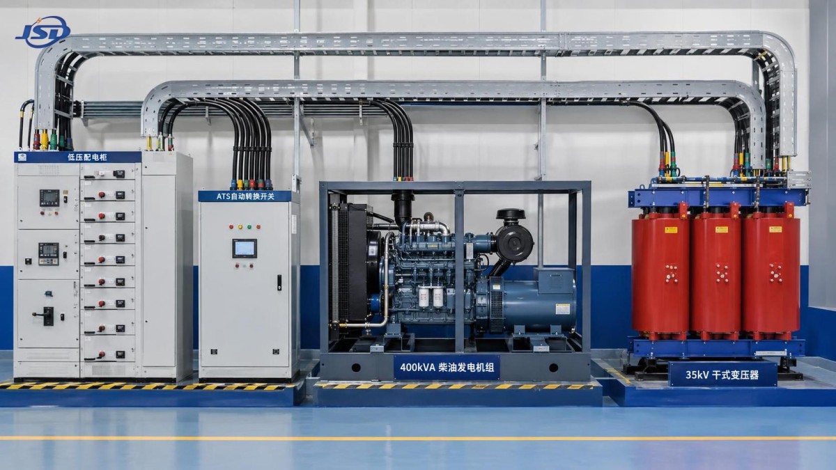
For example, a 35 kV to 0.4 kV distribution arrangement may use a cast-resin transformer upstream of the normal low-voltage board, with the generator connected on the low-voltage side through a suitably rated switching arrangement. In this type of layout, the transformer impedance, LV busbar rating, transformer secondary cable capacity, and generator breaker settings should be reviewed together. It is not enough for each item to be “400 V rated.” Their fault withstand, continuous-current capability, and selectivity must be compatible.
For projects requiring dry-type transformation in industrial plants, commercial buildings, hospitals, data centers, mining operations, or renewable-energy facilities, the 35kV Three-Phase Cast Resin Dry-Type Distribution Transformer can be considered within the broader distribution design. The SCB12 range is available for 35 kV input and 0.4 kV output applications, with capacities extending well beyond the generator rating. Selection still needs to account for actual demand, transformer impedance, ventilation, protection coordination, and whether the generator is intended to supply all transformer-connected loads or only an essential-load board.
This system-level view is central to Jinshida Electric Power Technology Co., Ltd.’s work in power transmission and distribution equipment. In practice, reliable backup power depends on the interfaces between equipment as much as on the equipment itself: cable terminations, bus connections, protection settings, earthing continuity, and maintainable access all deserve early review.
A practical cable-sizing workflow
Before issuing a cable schedule, collect the information that changes the outcome. At a minimum, confirm generator rated voltage and frequency, rated kVA and duty, alternator output terminal arrangement, circuit breaker frame and trip settings, route length, cable installation method, maximum ambient temperature, grouping conditions, conductor material, insulation type, load profile, and the receiving equipment’s required voltage tolerance.
Then perform the checks in a sensible order:
- Calculate full-load current from the confirmed generator voltage and kVA rating.
- Select preliminary conductor sizes using the applicable ampacity standard and the actual installation method.
- Apply temperature, grouping, enclosure, soil, or conduit derating factors as required.
- Verify voltage drop at continuous load and review the largest anticipated motor-starting or load-step condition.
- Check short-circuit thermal withstand and coordination with the generator breaker, ATS, and downstream protection.
- Confirm neutral and protective conductor requirements from the earthing system and load harmonics.
- Review physical installation: gland size, lug compatibility, bending radius, tray fill, phase identification, and equal routing for parallel sets.
The last item is easy to underestimate. A technically correct cable may not fit the generator terminal box, especially where multiple large parallel runs are required. Excessive bending force can damage lugs or stress alternator terminals. Cable termination details should be reviewed before delivery, not after the generator is already positioned on site.
Common decisions that create avoidable problems
One recurring mistake is sizing only to normal operating current and leaving no room for the actual environment. Another is increasing phase cable size to control voltage drop while forgetting that the neutral, earth conductor, cable glands, lugs, busbar links, and breaker terminals must still accommodate the revised design.
A third mistake is assuming that open frame means simple installation. Open-frame sets can offer convenient access, but they also expose the installation to dust, moisture, mechanical impact, UV exposure, and unauthorized contact unless the site arrangement is properly controlled. Cable type and mechanical protection should match the environment. A flexible temporary feeder, an armored buried cable, and a fixed indoor tray cable are not interchangeable simply because their conductor cross-section is similar.
The strongest cable plan for a 400 kVA generator is therefore not the one with the largest conductors. It is the one that has been checked against current capacity, heat dissipation, voltage performance, fault duty, protection settings, installation practicality, and the transformer-to-load distribution path. Once those conditions are confirmed, the final conductor arrangement becomes a defendable engineering decision rather than an optimistic estimate.

Get a Quote
Regardless of whether you require general advice or specific support, we are happy to help you.
Send Us Your Inquiry Today

Jinshida Electric remains committed to contributing to global energy development through professional manufacturing and superior service.